GreyMecha/Army v2
I did some stuff for GreyMecha/Army and GreyCTF2026. Most of it is in the slides, and I'll add additional things here and there
1. GreyCTF 2026 Context
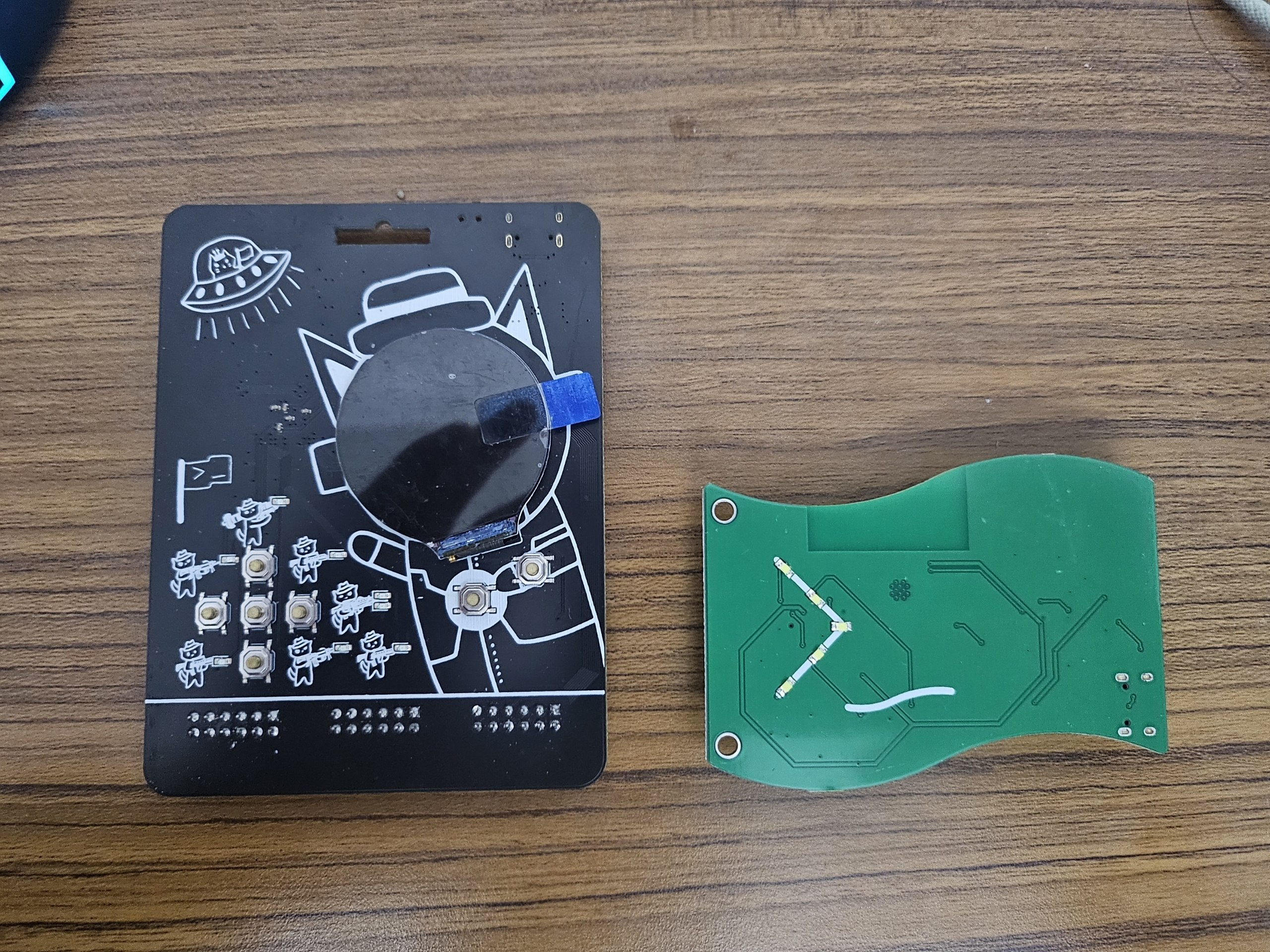
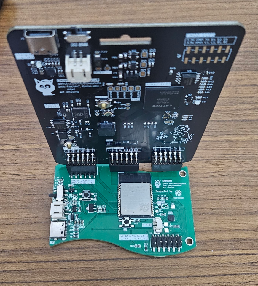
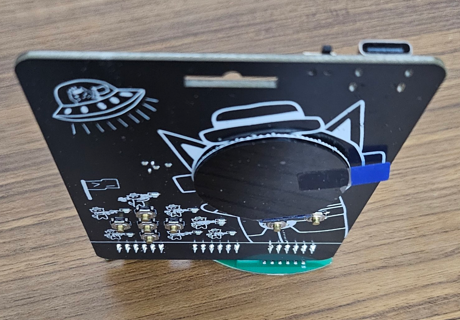
Anyway the context this year is that we provided everyone a GreyFlag PCB + a GreyMecha/Army v2. The GreyMecha/Army v2 mainly added PSRAM + Fixed the Flash + an extra PMOD.
GreyFlag was meant to pair with the plushie AND/OR the GreyMecha/Army v2. The firmware wasn't done in time
I came up with the idea but GreyFlag was designed by Restia.

1.1 Production Issues
Hackin7's Tinkering Log: Btw note to self for greymecha production delays
For greymecha I pulled the 2 layer stunt because I believed that it'll still work, and it'll be cheaper
I had valid reason too, if you look at other ECP5 Schematics, there weren't dedicated planes for grounding high speed signals, it's just all signal planes, so if you don't need so many signals you don't really need so many planes, other than for a vague reason like signal integrity
But in hindsight that cost us both a slightly worse board, and in production difficulties, because bga PCBA production capabilities are designed for multilayer boards, such as via in pad, it'll still work on 2 layer, but the manufacturer is just not as used to it I guess.
I guess next time for complex parts at large scales, just use 4 layer, it's not that much more expensive, it fulfils the signal integrity better and it also just better for manufacturers
Hackin7's Tinkering Log: Also my rough rule of thumb is that anything less than 100MHz I can get away with suboptimal routing
GreyMecha was a 50MHz PCB, but in hindsight if I handled the oscillators properly it could have been 400MHz with the PLL
I think with secure memory, one of the reasons we needed some histogram nonsense in the solution is due to the routing not being optimal
1.2 PIO
Did a deep dive in PIO during GreyCTF itself for my PIO challenge (turns out vibecoding the whole thing led to me not understanding🤡)
Some useful Resources
https://rp2040pio-docs.readthedocs.io/en/latest/architecture.html (cool emulator thingy)
Interesting notes
- Because PIO is so fast, you gotta switch it multiple times and sample multiple times, then use statistics to figure out what is the most likely value
- this probably happens due to the poor connection of the pins for the Secure Memory Challenge
- PIO reads pins in sequentially, no exceptions, so gotta proxcess in the CPU code, and focus on PIO for basic data input output
- There are basic synchronization primitives to pass data into and out of the PIO, which would be useful
In terms of setting challenges
- its always useful to provide more template code, especially in this AI Age
- Need to handhold on hardware connections, ctf players lowkey quite blur
From Restia
pio_input.py
-
I think that goes for most analog reads tbh, iirc ADC is 13x oversampling and your UART has oversampling as well iirc
-
When i was working with PIO, I remmeber for each state machine, you can only set 1 base pin, it you need to tell it how many pins to read beyond that also, and that it reads like pin Base then pin Base+1... up to 5 iirc but I couldn't get that to work so I just work with 1 input and 1 output lol. But there are 12 statemachines on rp2350 soo
-
The FIFO was quite useful for me, I remember to make my set up work, I used the fact that it was 32 bytes iirc and a blocking function call on my main loop so that the FIFO is always full and hence the pull from the PIO is accurate. Also learnt about OSR and scratch registers etc, all made me confused for a while quite cool
1.3 Watchdog KOTH Solutions
Yes in the watchdog challenge the watchdog is implemented on the FPGA in hardware.
We had a picorv32 core and I've added a watchdog timer that resets when it exceeds a certain value
Intented solution was to look for the Watchdog address by fuzzing, but tbh you could guess (uart is 0x1000000, led is 0x10000100, so judging by the spacing the next peripheral would be 0x10000200, which is where the watchdog would be)
Levels of Solution
- read character by character
- disable watchdog through fuzzing
- optimise by minimising loops, hardcoding address values, minimising operations,
- GCC O3 Compiler flag
- Assembly level optimisations (using
lborsbinstructions)
Other solutions
- hardcoding the flag would provide better performance, because it takes less clock cycles to load a hardcoded value than to read from memory mapped IO
smallest possible solutions are 0x150 for hardcoded flag, and 0x1a5 for non hardcoded solution
You can thank low level learning video series on hacking his baby monitor for this challenge, he had to code a bitcoin miner that bypassed the baby monitor's watchdog
2. Emulators
I did an Arduboy Emulator
https://github.com/Hackin7/GreyMechaArmy_Tests/tree/main/emulators/arduboy
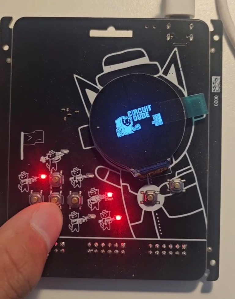
I did a Gameboy Emulator also
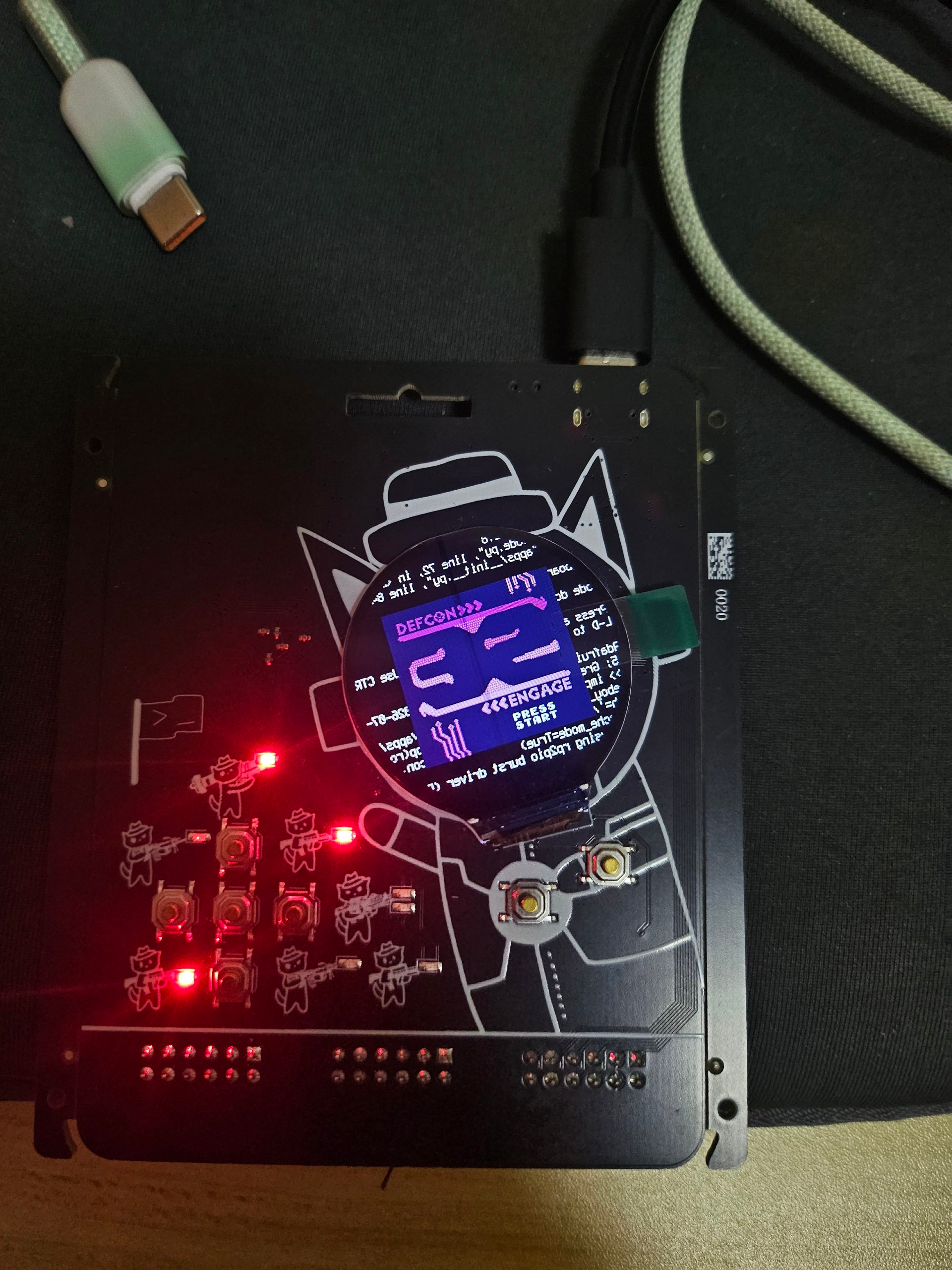
Just got Codex to port an FPGA emulators and softcores over
These are just for fun tbh