Hackbadge Hackery
Hackbadge to be honest is one of the most fun projects I have ever had the pleasure to work on. It was a relatively simple badge concept wise, but due to the nature of the CH32V003 and the requirement for Low Power and low cost it forced me to make some design decisions which I would not usually be exposed to.
Concept
So here are some concept messages:
| Messages |
|---|
| I think if we want to do a hackbash badge 1. we optimise for a metric besides computation/ hardware concept - Cost? - whats' the budget - Blinky/ look cool/ art? (Colour Printing? I have experience now) 2. Main aim should be to - Attract people to hackbash - Look cool - Encourage engagement with Hackbash - the reason I thought about this even was that last hackbash, we did certs, stickers giveaway to encourage people to come back the 2nd day. Maybe we can do this badge instead - it is NOT to challenge them hardware wise - that's for GreyCTF Think more SINCON style badges and less Off By One/ GreyMecha/Army |
| The goal is to blink blink and be happy maybe add flags to like encourage engagement then hardware flags can be like the tryhards |
I was heavily inspired by the f5 badge at BlackHat, one which aimed to change booth engagement with electronic badges. Maybe we can do the same for Secondary School/ Pre University Cyber Training?
Art
For a change of pace, I decided to handle the artwork entirely by myself. Generally in NUS Greyhats, I'm the person who is ideating the badge concepts and artwork.
I had some ideas for a Dog style badge in the past purely to contrast our predominantly cat badges LOL.
Another idea was to have 8 bit pixelated cats like so:
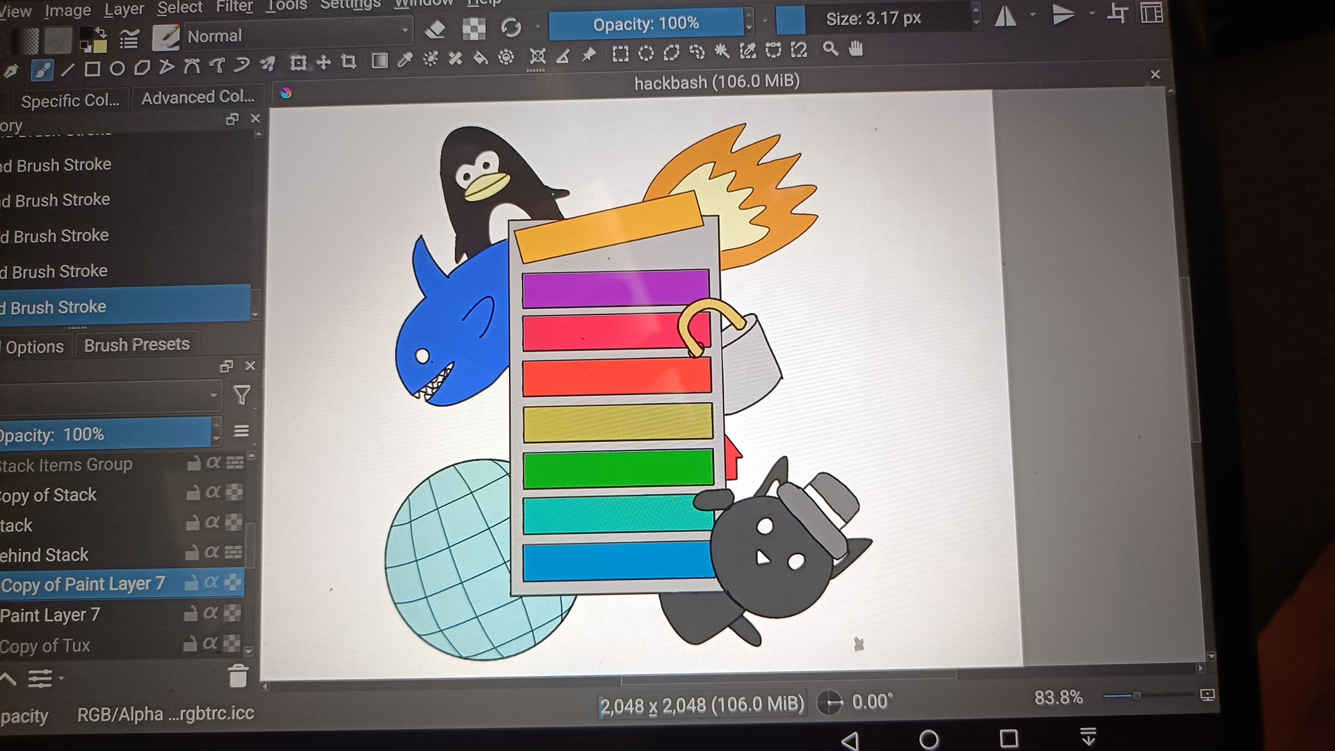
Eventually given the theme of Greycademy, I figured a StackOverflow kind of theme might fit nicer.
Each item in the stack will have an LED and you are supposed to overflow the stack. There would be different categories like web and crypto (lock) for unlockables
I then redrew in Krita and got out the artwork. I then extracted out the outline in inkscape and imported it into PCB design software. The image can be imported straight into EasyEDA.
PCB Design
Design wise we started out with KiCAD then moved to EasyEDA. The import tool in EasyEDA sucks apparently, so in hindsight should have done EasyEDA from the start.
I didn't have much hand in the design, other than setting the general guidelines such as what MCU to use, what functions the badge should have etc, deciding the rough layout. There isn't anything too noteworthy here I suppose (mousebites handled by JLCPCB)
Code
I worked mainly on the firmware on the badge. The main framework used is the ch32fun. I ended up not using the HAL Libraries and did most of the low level register coding.
I used the reference manual: http://nic.vajn.icu/PDF/WCH-IC/RISC-V/CH32V003_RM.pdf.
It was a fun exercise that got me to appreciate the peripherals of the MCU (there was code to copy anyway).
I worked with Interrupts, Timers, Flash Memory, and the Low Power modes. I want to go through some experiences working with peripherals
Timers
The Timers were really interesting to work on it, due to the way IO was muxed. The main reason we wanted to use Timers is for PWM of the LEDs to conserve power (and my eyesight
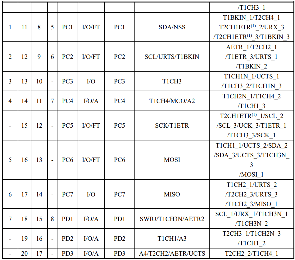
Looking at the pinout you would see some of the IO mappings. Unfortunately, I do not think there was an easy way to have done the schematic such that it would have been easy to use the timers, but maybe understanding the MCU before designing the schematic better would have helped.
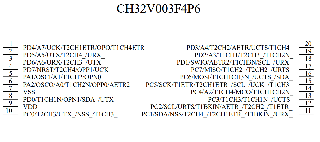
So most pins have a timer allocated to them, and thankfully all the LED pins chosen have a timer. However, the problem is that they do not have UNIQUE timers.
Which means that some LEDs have to reuse timers.
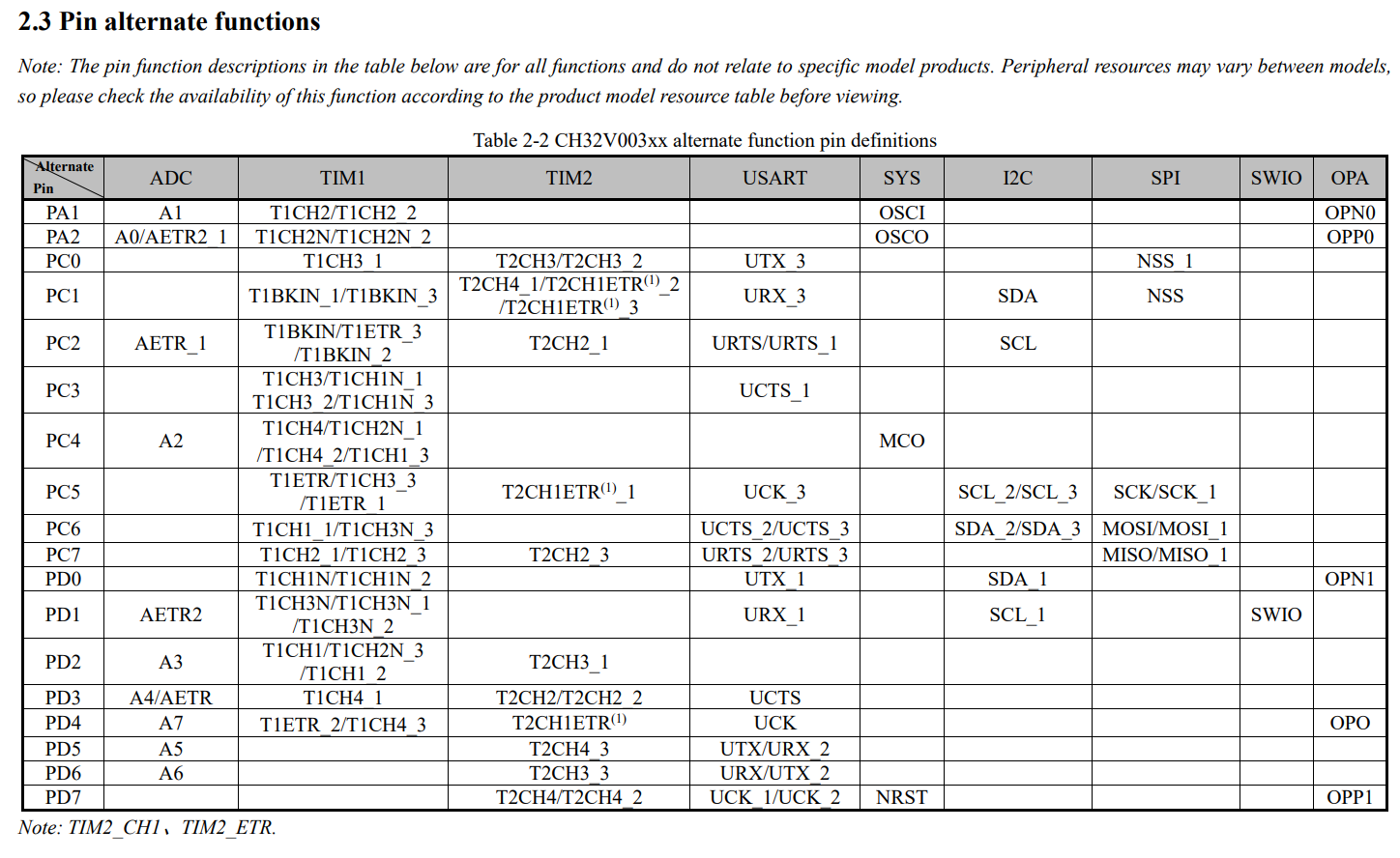
Furthermore, from the Reference Manual, there is only 1 alternative remapping mode.
We cannot selectively choose the timer channel only for that individual pin.
If we want to change the timer for that pin, we would need to change it for all other pins.
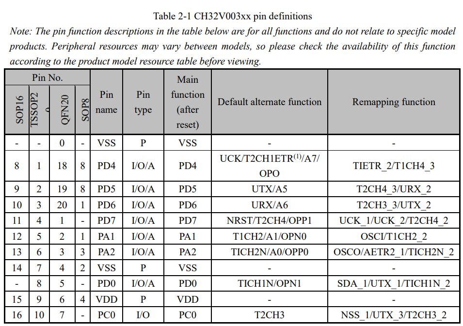
This means that if we want all LEDs to use the timer, we would need to switch between the different pin mappings in software (using the main CPU), like software PWM.
The concept of this is not new, and is in this example: https://github.com/cnlohr/ch32fun/blob/master/examples/tim2_pwm_remap/tim2_pwm_remap.c . However, the consequence of this is that the LED power sequence becomes very important. If you switch the IO mapping without turning off the LED, you would be left with some LEDs being on for a split second of time, short enough to be seen (as ironically, another form of PWM).
This was quite an interesting concept, and playing with it was quite fun. I had to
- find the best timer mapping (they all fit on 1 timer, so that was nice), and
- distribute each LED among the different pin mappings.
- After that in software, I'll mux between the modes, and
- enable the specific timer values for that pin.
void LED_PWM_Pass(int purple, int red, int orange, int yellow, int green, int blue){
    // Purple
    // Delay_Ms( 1000 );
    t1pwm_clear(0);
    AFIO->PCFR1 &= ~AFIO_PCFR1_TIM1_REMAP_FULLREMAP;
    funPinMode(PD2, GPIO_Speed_10MHz | GPIO_CNF_OUT_PP_AF );
    funPinMode(PC7, GPIO_Speed_10MHz | GPIO_CNF_OUT_PP_AF );
    funPinMode(PC6, GPIO_Speed_10MHz | GPIO_CNF_OUT_PP_AF );

    t1pwm_setpw(0, red);
    #ifdef LED_USE_TIMER2
        t2pwm_setpw(1, purple);
    #endif
    t1pwm_setpw(3, blue);


    // Delay_Ms( 1000 );
    t1pwm_clear(0);
    funPinModeClear(PC4, 4);
    AFIO->PCFR1 |=  AFIO_PCFR1_TIM1_REMAP_PARTIALREMAP1;

    t1pwm_setpw(0, yellow);
    t1pwm_setpw(1, orange); // linked to blue?
    #ifndef LED_USE_TIMER2
        t1pwm_setpw(3, purple);
    #endif

    // Delay_Ms( 1000 );
    t1pwm_clear(0);
    funPinModeClear(PD2, 2);
    funPinModeClear(PC7, 7);
    funPinModeClear(PC6, 6);
    AFIO->PCFR1 |=  AFIO_PCFR1_TIM1_REMAP_PARTIALREMAP2;
    funPinMode( PC4, GPIO_Speed_10MHz | GPIO_CNF_OUT_PP_AF ); // BLUE
    t1pwm_setpw(2, green);
}
Low Power Modes
So 10h before Greycademy, an important issue surfaced.
The badge was meant to be distributed to Greycademy participants, run on a coin cell battery. But after about 2min, the badge would brown out and shut off. One of my friends identified that the dropout voltage of the ch32v003 was too low, and given the battery chemistry, it just wasn't feasible. However, given that I saw other projects with the same MCU also, I refused to believe there wasn't a way with existing hardware. An example project is https://github.com/wagiminator/CH32V003-GameConsole, which used a CH32v003 and a coin cell battery.
I looked into the low power modes and clock speed registers in the user guides. I wondered what if I entered the low power mode but did not re-enable all the normal peripherals and system clocks. In practice, this means that the MCU would be using the low speed oscillator instead of a higher clock speed.
The result is that the badge worked much more reliably on the coin cell, resulting in at least a 90x improvement in battery life (I did not scientifically calculate this). Given my internship experience and my digital design experience with peripherals and clock gating, and even the theoretical experience in school modules, a lower clock speed would cause less switching and dynamic power consumption. Yet nothing beats seeing it in action.
I could have optimised it further by leaving the MCU mostly in sleep mode and only turning it on, but at that point it worked well enough so I moved on quickly, fixed code, took a nap, rushed to school and reprogram.
	// enable power interface module clock
	RCC->APB1PCENR |= RCC_APB1Periph_PWR;
	// enable low speed oscillator (LSI)
	RCC->RSTSCKR |= RCC_LSION;
	while ((RCC->RSTSCKR & RCC_LSIRDY) == 0) {}
	// enable AutoWakeUp event
	EXTI->EVENR |= EXTI_Line9;
	EXTI->FTENR |= EXTI_Line9;
	// configure AWU prescaler
	PWR->AWUPSC |= PWR_AWU_Prescaler_4096;
	// configure AWU window comparison value
	PWR->AWUWR &= ~0x3f;
	PWR->AWUWR |=   1; // immediately wake up
	// enable AWU
	PWR->AWUCSR |= (1 << 1);
	// select standby on power-down
	PWR->CTLR |= PWR_CTLR_PDDS;
	// peripheral interrupt controller send to deep sleep
	PFIC->SCTLR |= (1 << 2);

    // mode_ctf_main();
    debug_print("Welcome to Hackbadge\n");
    ModeBlinky_Setup();


    __WFE();
    // SystemInit(); // the special line commented out
The code I referenced was here: https://github.com/cnlohr/ch32fun/blob/master/examples_x00x/standby_autowake/standby_autowake.c
Interrupts
Nothing too special other than that both buttons share the same interrupt line (pressing either button would trigger the same IRQ) so logic needs to be done to handle that.
Flash Memory
Generally the code is the same as GreyCat, and most of the code was copied & modified for the ch32fun framework.
If there is one pointer I'll like to take note, it would be this:
- If you do not erase the flash (set all the bits to 1), on writing to the flash, you can only clear the flash bits, not set any new bits. I spent a fair bit of time on this issue.
ADC
So sound is a wave, and as such, when using the ADC to measure volume, you can calculate the volume using the Peak to Peak value, not just the raw magnitude.
I didn't exactly implement the code (sayo did) but I did give the idea sometime ago.
Other Features
Some other features I was thinking about were native USB support (the USB bootloader works on the badge), but due to time and size constraints I cut them from the final badge. I wouldn't want people just dumping firmware so easily anyway.
Conclusion
Overall it was a fun badge to play with and work on. From what I see some participants at Greycademy engaged a fair bit with it and put it even on their social media, which was nice.
Appendix: ChatGPT Summary of Handling the Toolchain
Sure — here’s a tight, condensed walkthrough that keeps the essentials and reads like a checklist, without a bunch of section headers.
Install dependencies in Linux/WSL:
sudo apt-get update
sudo apt-get install -y build-essential libnewlib-dev gcc-riscv64-unknown-elf \
  libusb-1.0-0-dev libudev-dev gdb-multiarch
Clone rv003usb into your project and build it:
git submodule add https://github.com/cnlohr/rv003usb.git code/env/rv003usb
cd code/env/rv003usb
git submodule update --init --recursive
make
Build minichlink and optionally install it system-wide:
cd ch32v003fun/minichlink
make
sudo cp minichlink /usr/local/bin/minichlink
Set udev rules so Linux can access the WCH-LinkE and rv003usb without sudo:
sudo tee /etc/udev/rules.d/99-wch-link.rules <<EOF
SUBSYSTEM=="usb", ATTR{idVendor}=="1a86", ATTR{idProduct}=="8010", MODE="0666"
EOF

echo 'SUBSYSTEM=="usb", ATTRS{idVendor}=="1209", ATTRS{idProduct}=="b003", MODE="0666"' \
| sudo tee /etc/udev/rules.d/50-rv003usb.rules

sudo udevadm control --reload-rules
sudo udevadm trigger
On Windows (PowerShell as admin), attach USB devices to WSL:
winget install usbipd
usbipd list
usbipd bind --busid 2-3
usbipd attach --wsl --busid 2-3
Verify inside WSL:
lsusb
# should show: 1209:b003 Generic rv003usb
Configure USB pins in bootloader/usb_config.h (Port C, DP=PC1, DM=PC3, DPU=PC0 or per your wiring).
Optionally increase bootloader timeout in bootloader.c:
#define BOOTLOADER_TIMEOUT_PWR 670
Build and flash the bootloader (manual flash is important):
cd bootloader
make
minichlink -E
minichlink -a -w bootloader.bin 0x0000 -B
View USB printf/debug output:
minichlink -T
Build application code (example):
cd code/tests/timer_pwm
make
Flash application over USB:
sudo minichlink -w breathing_led.bin 0x08000000 -c 0x1209b003 -b
If using a ~1920-byte bootloader, update the linker script:
FLASH (rx) : ORIGIN = 0x00000800, LENGTH = 14K
Then flash apps at the offset:
sudo minichlink -w CH32V003A4M.bin 0x00000800 -c 0x1209b003
Notes: every time the USB is unplugged or WSL restarts, you must re-attach it with usbipd. If flashing works but code doesn’t run, check clock speed, flash origin, and bootloader timeout.