Quack & Roll: Making a Badge for 1000+ participants
This blog post was presented as a Friday Hacks FH#287, the slides available at https://docs.google.com/presentation/d/1HqQwvpg1HEM3IlgGZw1MMopxqhB1Y3bP6d3GQiEREJI/edit?usp=sharing
Intro
So 10 years ago, in 2016, people from NUS Hackers helped NUS Greyhats make the first every NUS badge for XCTF 2016, the Neander.
10 years later in 2026, people from NUS Greyhats have finally repaid the favour by helping make the Hack & Roll 2026 Badge.
1. Ideation
It all started when Yik Jin was inspired to start working on an Electronic Badge for Hack & Roll, and he shared the idea with me. Having just went to DEFCON previously, and saw how badges were used to engage a large crowd, I could see the potential, such as audience engagement with the F5 badge (I played the CTF), and with Badge Hacking. I was especially intrigued by the idea of Badge Hacking, since Electronic Badges contain so much technology, it'll be a waste to just use them for only one thing.
From what I understand, the timeline was tight, but 4 months (October - January) is more than enough to fit in a schedule to do a Badge. After some discussion, I decided to, in my words: "Help NUS Hackers scale from making 50 badges to making 1000+".
1.1 Concept
Before we started, we clarified why we wanted badges, and we settled on these 3 reasons
- They are COOL
- We use them to track Food Collection Status & Engagement
- We want Hackability and to raise the level of Hardware Hacks
1.2 Artwork
We had some ideas for art work, some of them include
- Quackers Tamogachi
- Quacker's head that attaches to a body
- Quackers Hacking on a laptop
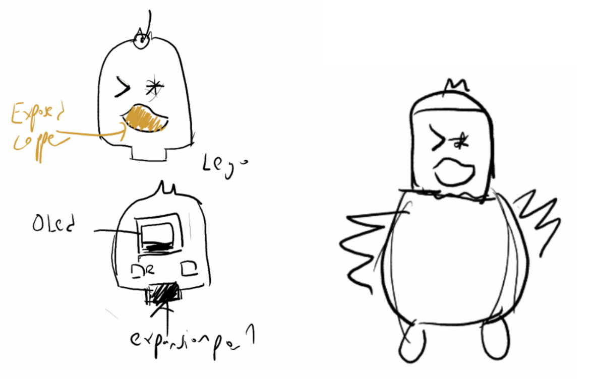
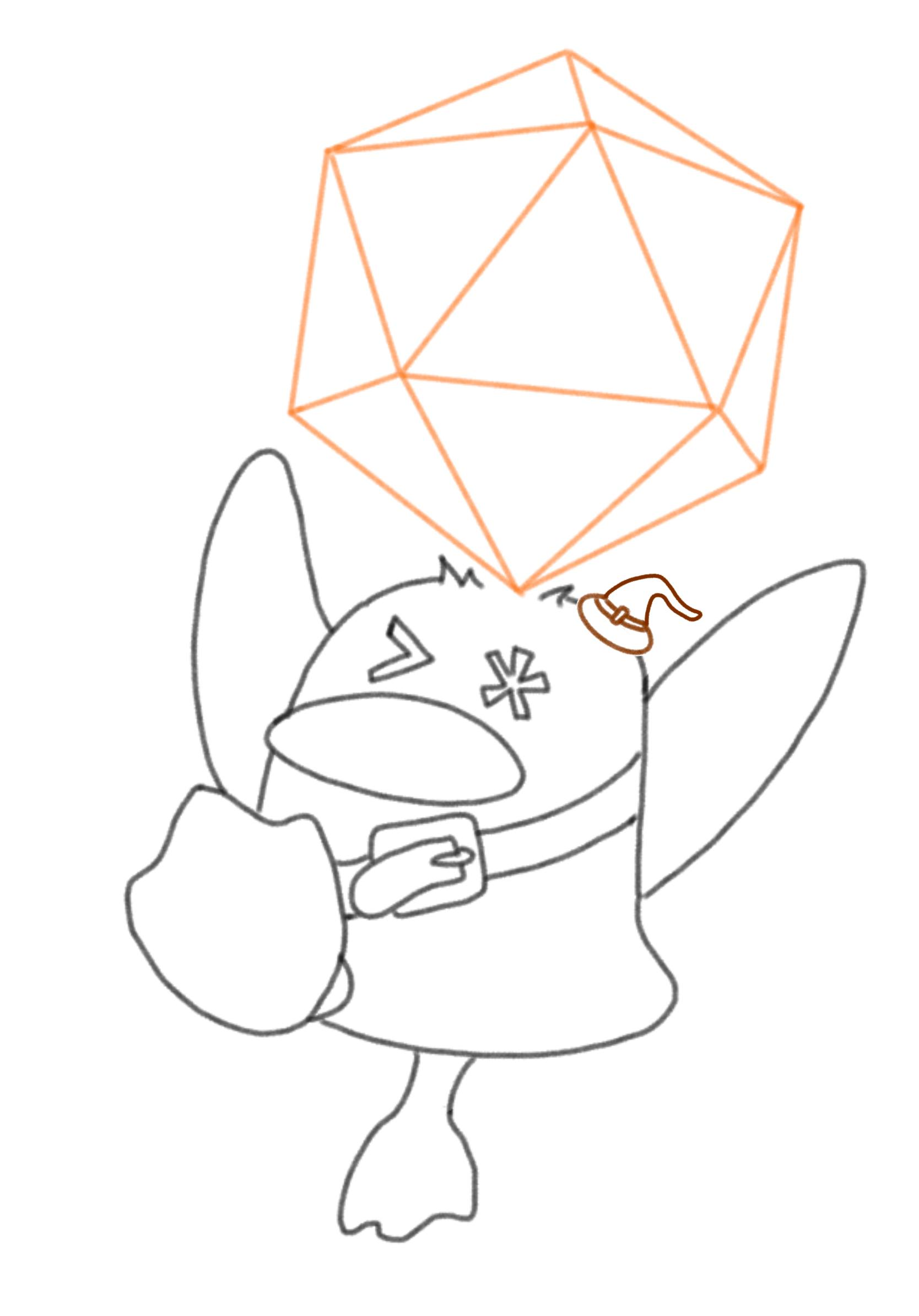
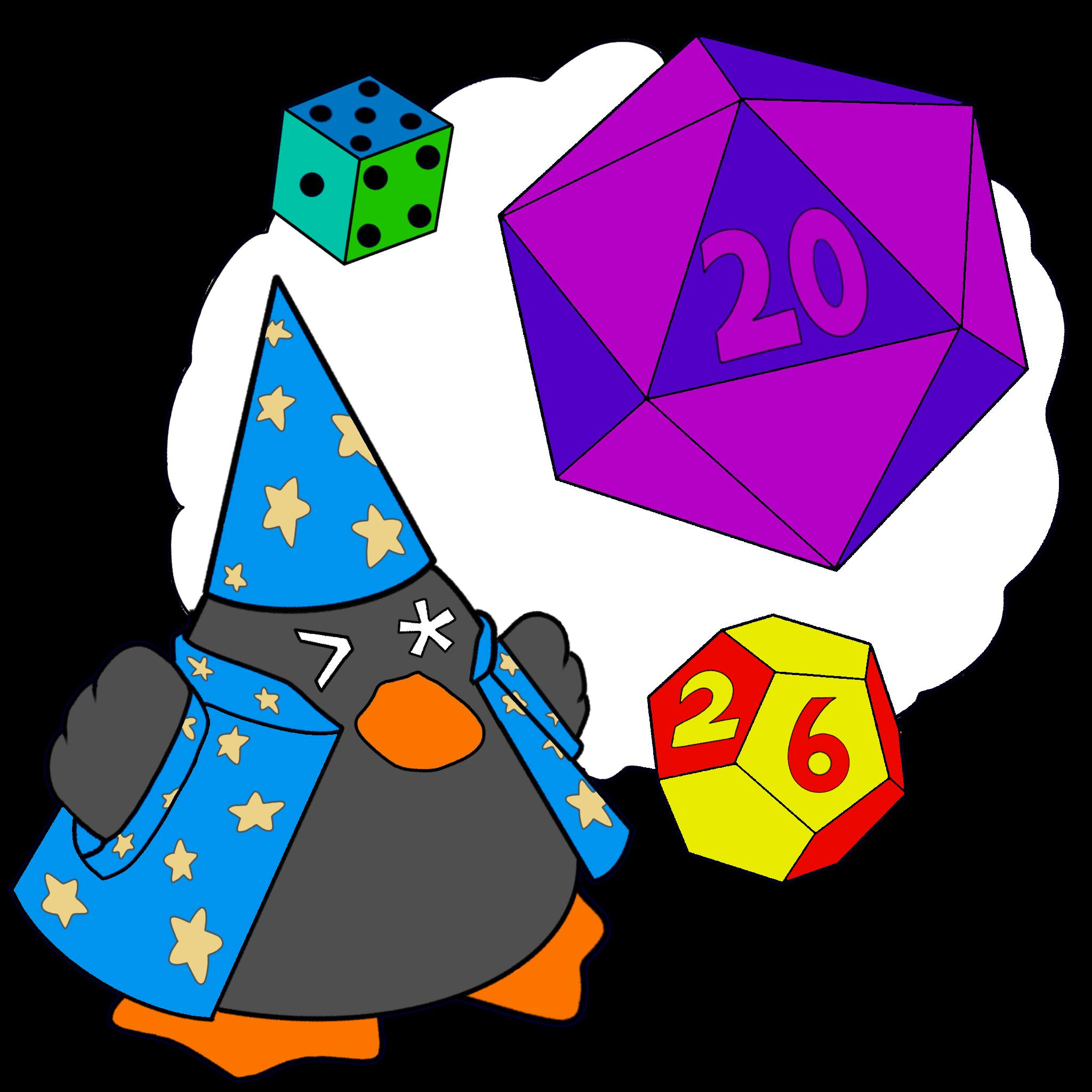
As the theme of this Hack & Roll was D20 and "Roll the Dice", we decided to look in that direction, and eventually, we decided on a theme of Quackers with a Dice. I had some ideas of how it could be.
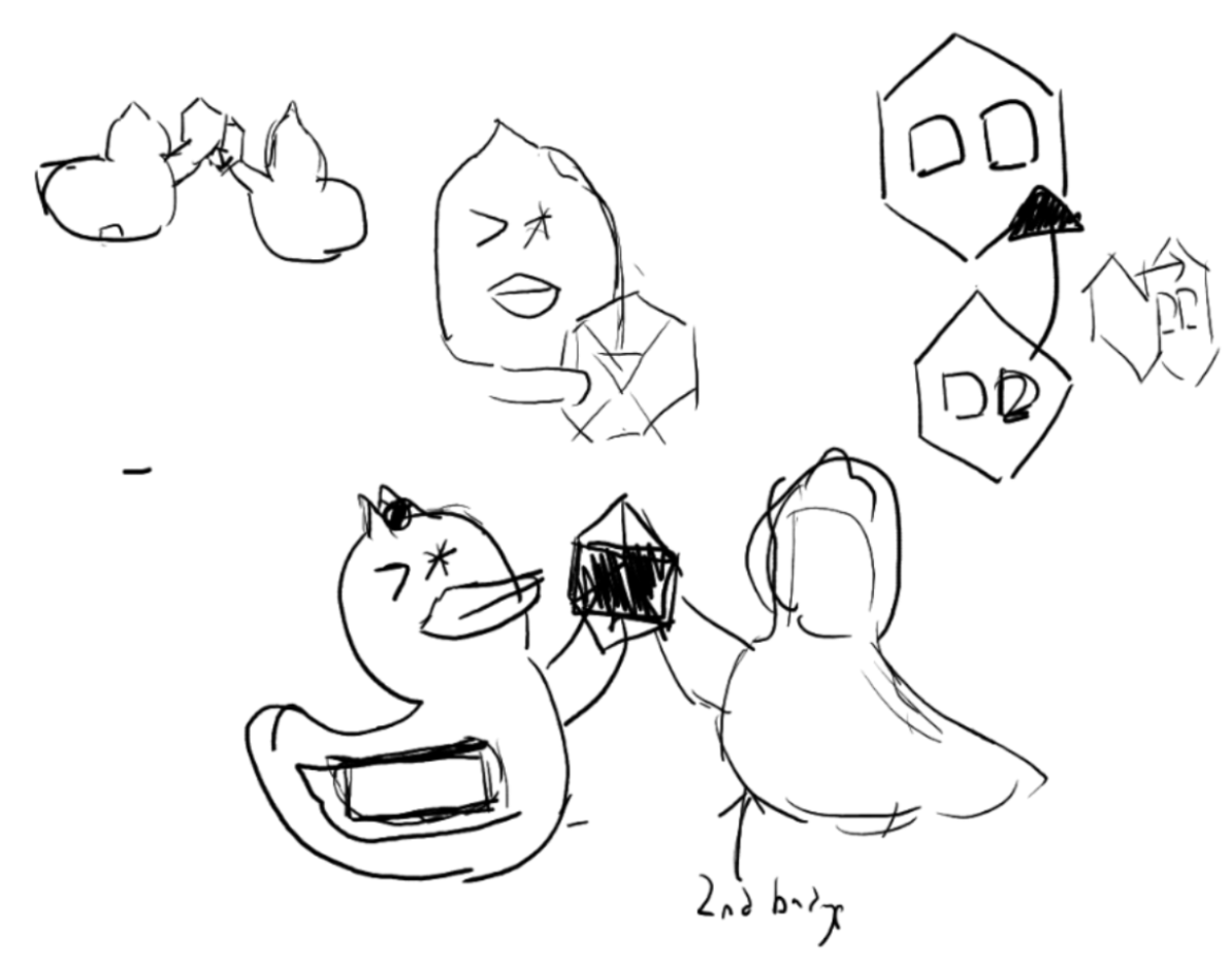
Youngseo did some redraws and the initial design was something like this. I tried my best to do PCB Routing with this design, but quickly realised it would not fit the battery holder, even if we stack it on top of the components. I had to ask for a different design, one with more space to work with.
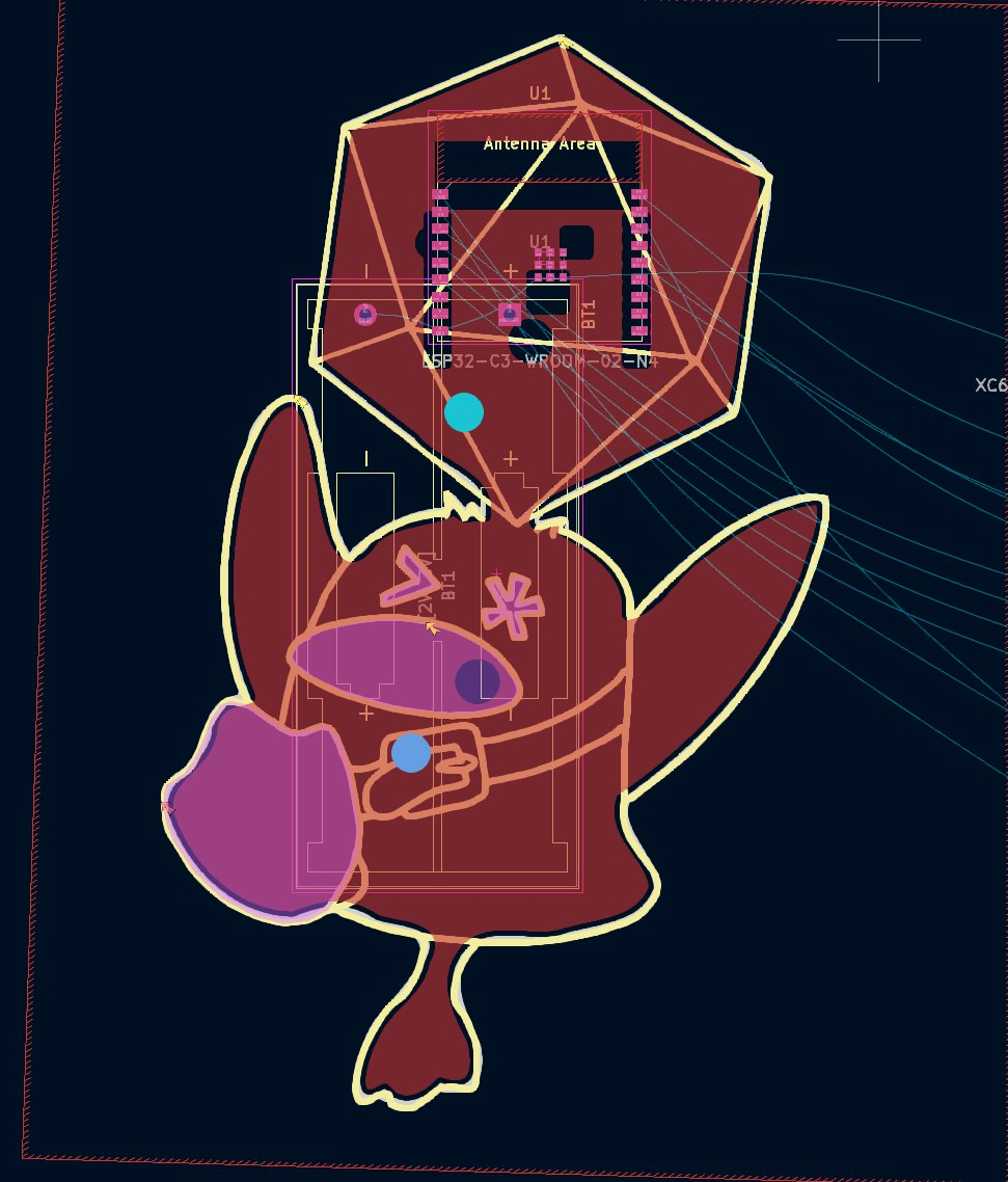
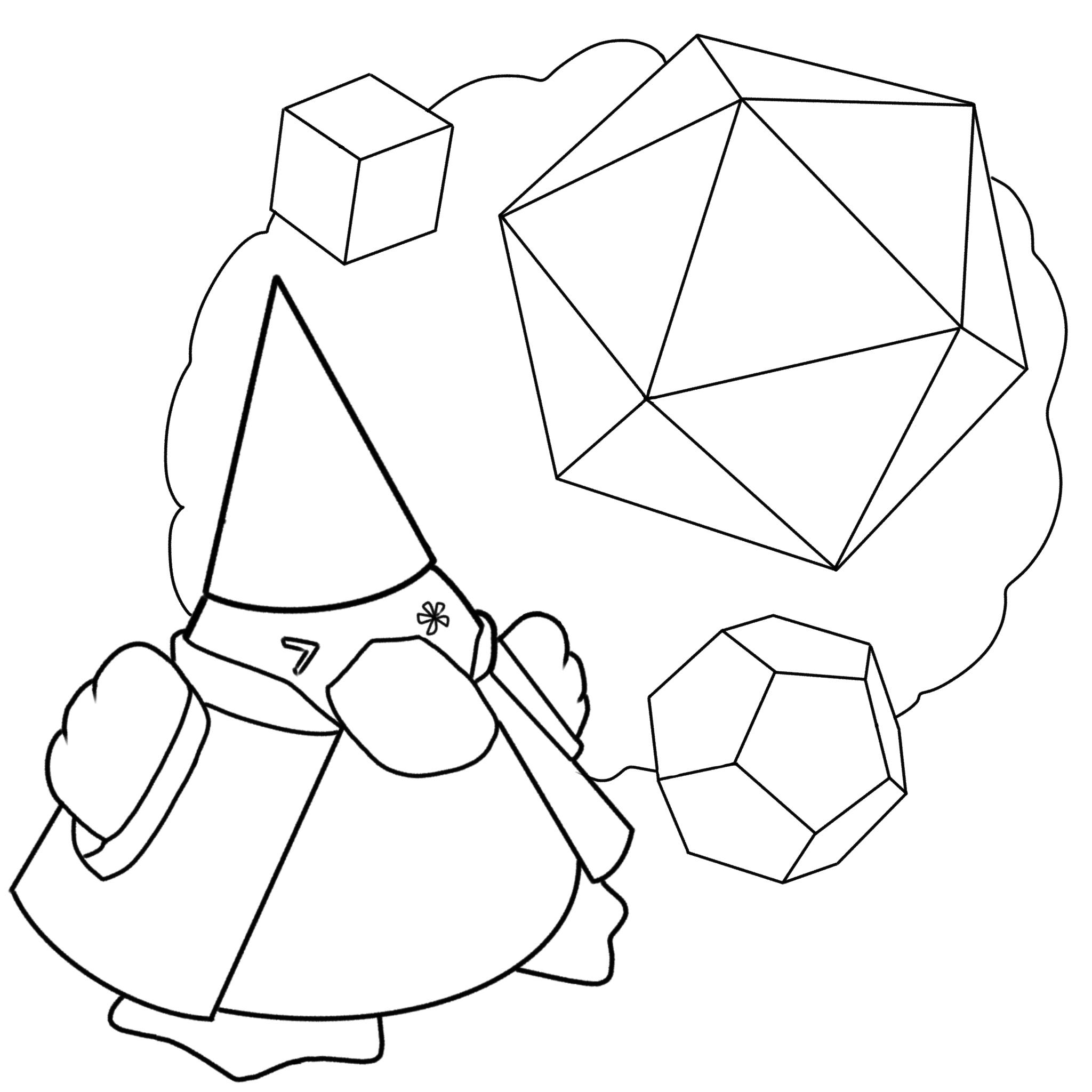
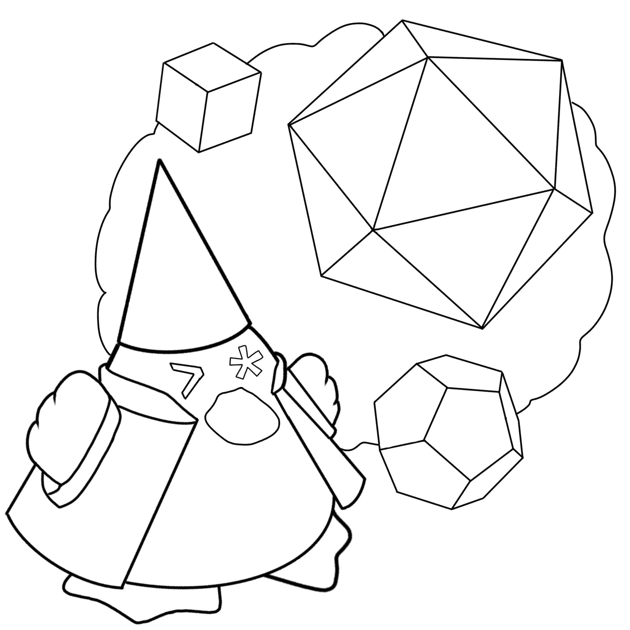
Youngseo cooked with the next designs, and we went with these overall designs. I also asked for a colouring in the event we wanted to do a colour PCB
2. Hardware
Design Choices
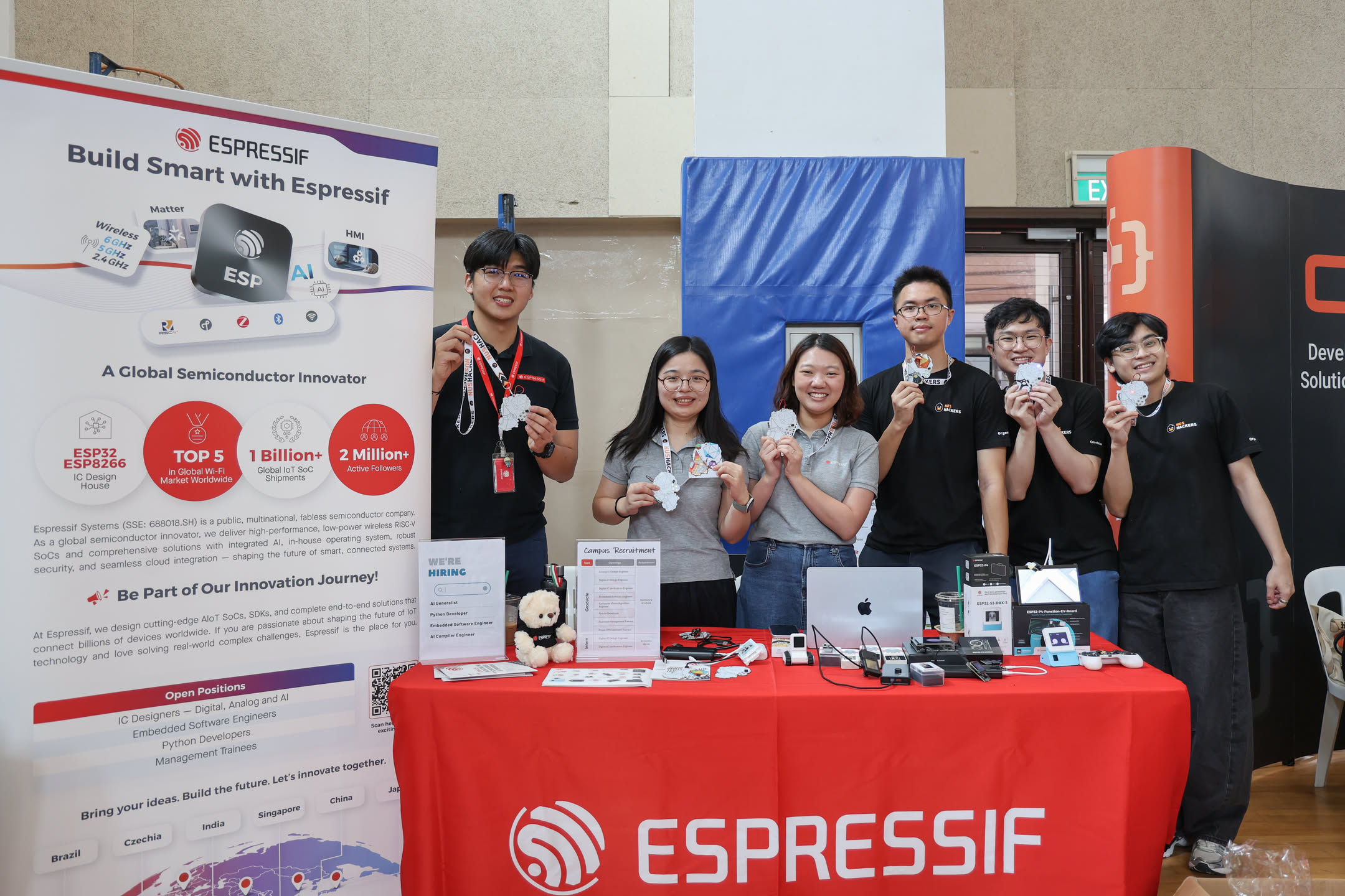
For our Microcontroller we went with the ESP32 module due to its wireless capabilities (WiFi, Bluetooth), and its ease of use. With support for MicroPython, participants can easily get started programming the badge. The ESP32 C3 was one of the cheapest and easiest to use modules, and furthermore, Espressif sponsored all the modules used through JLCPCB consignment.
I personally didn't do all of the schematic, but I had a hand in reviewing the schematic.
There were some tricks done such as
- Implementing a USB ESD Chip for protecting the circuits
- Since the ESP32 C3 has a very sensitive voltage range (at 2.9V it will stop working), we added a boost to 3.3V from the 3V AAA battery
- Adding an SAO port for expandability
- Since the ESP32 C3 has limited IO, and as such , an external IO expander was used to support more LEDs and buttons
At one point, we were considering having an OLED screen. However, there were various reasons we decided against that.
- Implementing an OLED straight through JLCPCB would require more components and validation of the OLED schematic, which would take time.
- Using an OLED module would mean an increase in assembly costs
- Eventually, I also realised that an OLED would mean people would instinctually default to it for displaying anything on the badge, when I wanted them to be more creative and invent ways with the other methods, such as the buzzer and the LED Dice.
Prototype 1 - The jloh badge
Usually for PCBs once we have a design, there's a few steps to convert the art work into something that can be used. Here are some of the rough steps:
- Open the svg in inkscape
- Extract out outline
- Simplify path, then break path import
After that is done, I came up with a rough layout of the ESP32
After that, one of the days in Shanghai I just speedrun routing from 10pm to 2.34am. Furthermore the initial plan was a black PCB for Quacks (which is coloured black), but we eventually decided that we can try white.
Yes, jloh behind the battery is an intentional feature.
Prototype 1 Tests
Most of the functionality of the boards worked. On a hunch, I tried buying some colour makrers and colouring, similar to what happened at the ICS Village Badge at DEFON, I realised there was potential in allowing the participants to colour a full badge.. Every badge would be unique and this would allow for great ownership. Anyone can colour the PCB and make it their own.
Prototype 2 - NFC
The first prototype was mainly to validate the components. The second prototype was to refine the layout and design.
There were some changes such as
- Redesigning the credits and Silkscreen
- Changing the LDO from 300mA current to 1A current (AMS1117)
- Moving/ Removing the buttons to make space for NFC
- Exposing more pads for hackability and debugging
Due to miscommunication, we did not scope for NFC in the initial project. But since there was time, I tried to implement a simple NFC Tag. I went to JLCPCB and searched for a cheap NFC tag chip, the NT3H2111W0FHKH
To generate the NFC Tag coil, I used a python script online, at https://github.com/nideri/nfc_antenna_generator. Looking by guides online, it seems that super strict impedance matching was not required to get something that works. I also tried to keep the NFC coil away from the components to ensure that there would not be any unwanted induced currents.
However, since the NFC chip intentionally supports power over I2C, I intentionally exposed the chip's I2C pads for easy access so that those skilled enough can reprogram the tag. In the end, there was a Hack & Roll Project that tried to do this, called "wayside"
Name of the Badge
I wanted a cool name for the badge, just like how people call the GreyCTF badge GreyMecha/Army. I came up with the idea of the Quack & Roll name because there was Quackers and it was rolling the dice. After some back and forth, I thought maybe a light novel title would fit the badge well.
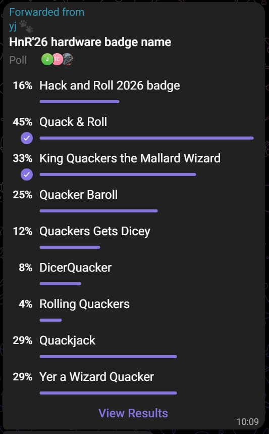
Full name:
Quack & Roll: King Quackers the Mallard Wizard of King Gizzard and the Lizard Wizard, the Hack and Roll 2026 Badge
Short form:
Quack & Roll Badge
3. Firmware
ESP-IDF Library
Most of the code was not done by me, and instead done by Yik Jin, but it is basically a wrapper around the aw9523 IO expander library. I had a hand in setting up NUS Hackers' ESP Component Registry accounts, and publishing it on there.
Referring to this guide helped, Espressif Documentation is usually quite well structured so there were not too much issues (besides dumb ones).
https://docs.espressif.com/projects/idf-component-manager/en/latest/guides/packaging_components.html#publish-your-component
This was mainly done for hackability, but also to support the ESP IDF workshop.
MicroPython Firmware
Early on, the Firmware was decided to use MicroPython for ease of use. MicroPython was a stable in various other badge firmware. Some other considerations were that
- CircuitPython (the framework used for GreyMecha/Army) was not stable enough on testing
- I wanted participants to easily start programming on the badge, and MicroPython allowed that with the Web IDE (Adafruit CircuitPython Web IDE)
There were some ideas I had for Badge Modes
- LED Blinky modes
- Random
- Music
- Faces (After asking around for feedback)
- Dice Game
- Sponsor Upload/ Download mode
Some Considerations
- 1 button to change mode - so if any issues, I can tell them to just press that button to play with the badge
- I used software PWM to dim the lights such that it would not be so bright. Despite this, at the event, I think lighting up 1 LED at a time at full brightness worked quite well, considering all the lighting considerations.
The Music Framework uses existing RTTTL Players from past projects. The Music was transcribed by hand by me, I took 2 songs from GreyMecha/Army and added mainly songs used by NUS Hackers in publicising Hack & Roll 2026. If you notice, 1 of the "song" is actually inspired by jloh promoting Hack & Roll! Do try to find it!
I used these for RTTTL Composers online to help me
https://corax89.github.io/esp8266Game/soundEditor.html
Badge to Badge Communication
Contact Pads
Due to the unique (bad) way I implemented the contact pads using the IO expander, I had to bitbang communication protocols. I tried to ChatGPT some rough classes for testing
- UART worked somewhat, but it was prone to errors and corruption. Adding Error correction had issues too
- I2C just didn't work.
After spending 2 full days on it, and finding no good way to handshake between master and slave (and deciding who was the master or slave) in time, I gave up and concluded that the contact pads were a bust. I then moved on to another more reliable and known way to implement this.
Bluetooth Low Energy Data Transmission
The Bluetooth Low Energy modes did not work well on the AAA Batteries in the end, so that we had to use a powerbank for this mode.
The aioble library had decent documentation, so I mainly refactored that to allow for sending of files
The way it works is as such
- On triggering Bluetooth connection, It'll first wait for a random amount
- This would ideally prevent collisions as much as possible
- It then goes to client mode to find a server
- If that times out, it then goes to a server mode
- Once connected, the server sends text data to the client over the BLE characteristic
Dice Mode
One reason we wanted Badge to Badge Communication is to encourage people to use the badge more!
The way the Dice Mode works is quite simple:
- Connect 2 badges through BLE
- The server badge sends the LED pattern and number of times to blink/ led list to blink
- There is a count left, count right, and random mode
- Both show the pattern at the same time (no other synchronization over BLE)
- based on the random number sent and whether the current badge is server or client, a "winner is decided", and only that badge has their LED lit up in the end
- The idea behind this is to implement a win state so that it would be more satisfying
In hindisight I realised this bagde
The Dice Mode works on a single badge too, so do try that out!
Sponsor Upload Download Mode
This was one of the ideas I had when doing the Hack & Roll Badge. Similar to Black Hat F5 badge, I was wondering if we could bring around the badge to unlock other LED patterns.
On a technical level, it was basically going to a booth with a Server, and downloading a Python file from there (it worked decently fast, though not the best). The main Application code would check for downloaded files and load them/ handle any errors on runtime. I did try to do that for the Espressif booth as a testbed, but due to the unstable nature of the communication (needs Power Bank to avoid brownout), and Espressif having so much other things to showcase, it did not go through in the end. Nevertheless, it was a fun exercise!
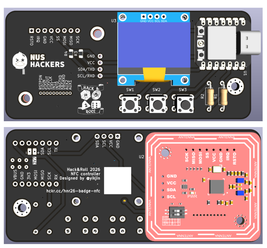
4. NFC PCB
Most of it was handled by Yik Jin, but the rough idea is to have an extra PCB to allow us to easily scan the participant's badges. Custom hardware was decided as the best option since
- It is not intuitive to use Android/ iOS (Especially iOS) Web NFC APIs to scan the tag.
- External NFC Readers are clunky to bring around
- With custom hardware, we can make it easy to pick up and play, to minimise setup time
Hardware
I had some design considerations
- Off the shelf modules for ease of usage/ soldering. The timeline was rather tight and the quantity was rather small for PCB Assembly.
- OLED for feedback + Buttons for usage
- NFC Module
Other than that, not much big issues here, at least in designing.
Arduino Code
Having worked on NUSC Laundrobot, I had experience creating simple IoT devices which connected to NUS Wifi. Coming up with code to
- read the NFC Tag using the PN532 module
- send the Tag ID to the API
is not too bad.
I prepared sample Arduino Code for use just in case the CircuitPython one failed or was too troublesome. In the end, it was also deployed on some boards and used just in case.
#include <WiFi.h> //Wifi library
#include <HTTPClient.h>
#include "esp_wpa2.h" //wpa2 library for connections to Enterprise networks


const char* ssid = "NUS_STU"; // Eduroam SSID
const char* host = "www.google.com"; //external server domain for HTTP connection after authentification

int counter = 0;

void wifi_scan(){
  int n = WiFi.scanNetworks();
  for (int i = 0; i < n; ++i) {
      Serial.print("SSID: "); Serial.println(WiFi.SSID(i));
      Serial.print("BSSID: "); Serial.println(WiFi.BSSIDstr(i)); // Prints BSSID as string
      Serial.print("Channel: "); Serial.println(WiFi.channel(i));
      // Store the BSSID and channel of your target AP
  }
}

void wifi_connect(){
  Serial.println();
  Serial.print("Connecting to network: ");
  Serial.println(ssid);
  WiFi.disconnect(true);  //disconnect form wifi to set new wifi connection
  WiFi.mode(WIFI_STA); //init wifi mode

  // Example1 (most common): a cert-file-free eduroam with PEAP (or TTLS)
  WiFi.begin(ssid, WPA2_AUTH_PEAP, EAP_IDENTITY, EAP_USERNAME, EAP_PASSWORD);

  while (WiFi.status() != WL_CONNECTED) {
    delay(500);
    Serial.print(".");
    counter++;
    if(counter>=60){ //after 30 seconds timeout - reset board
      ESP.restart();
    }
  }
  Serial.println("");
  Serial.println("WiFi connected");
  Serial.println("IP address set: ");
  Serial.println(WiFi.localIP()); //print LAN IP
}
CircuitPython Code
I had a vision of eventually using CircuitPython due to the ease to make changes to the code at site, which paid off.
In hindsight, if I knew how much effort it took, I would never have asked for CircuitPython.
We had issues with trying to get the Wifi and the PN532 AND the OLED libraries loaded, as loading them would cause an Out Of Memory Error. Changing the CircuitPython version fixed the problem, but finding that out was very painful for leyew. Leyew did manage to use Codex to add WPA2 Enterprise support to CircuitPython, which is quite amazing ngl.
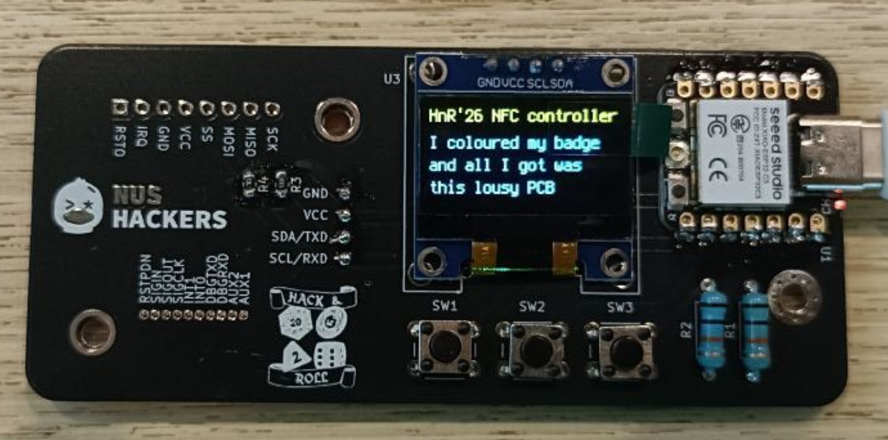
Usage
As an idea, to mimic last year's Quackers' Commendation award (it's just a towel saying "I won Hack & Roll and all I got was this lousy towel"), I decided to display it on the badge too and give out as colouring contest prizes!
5. Operations
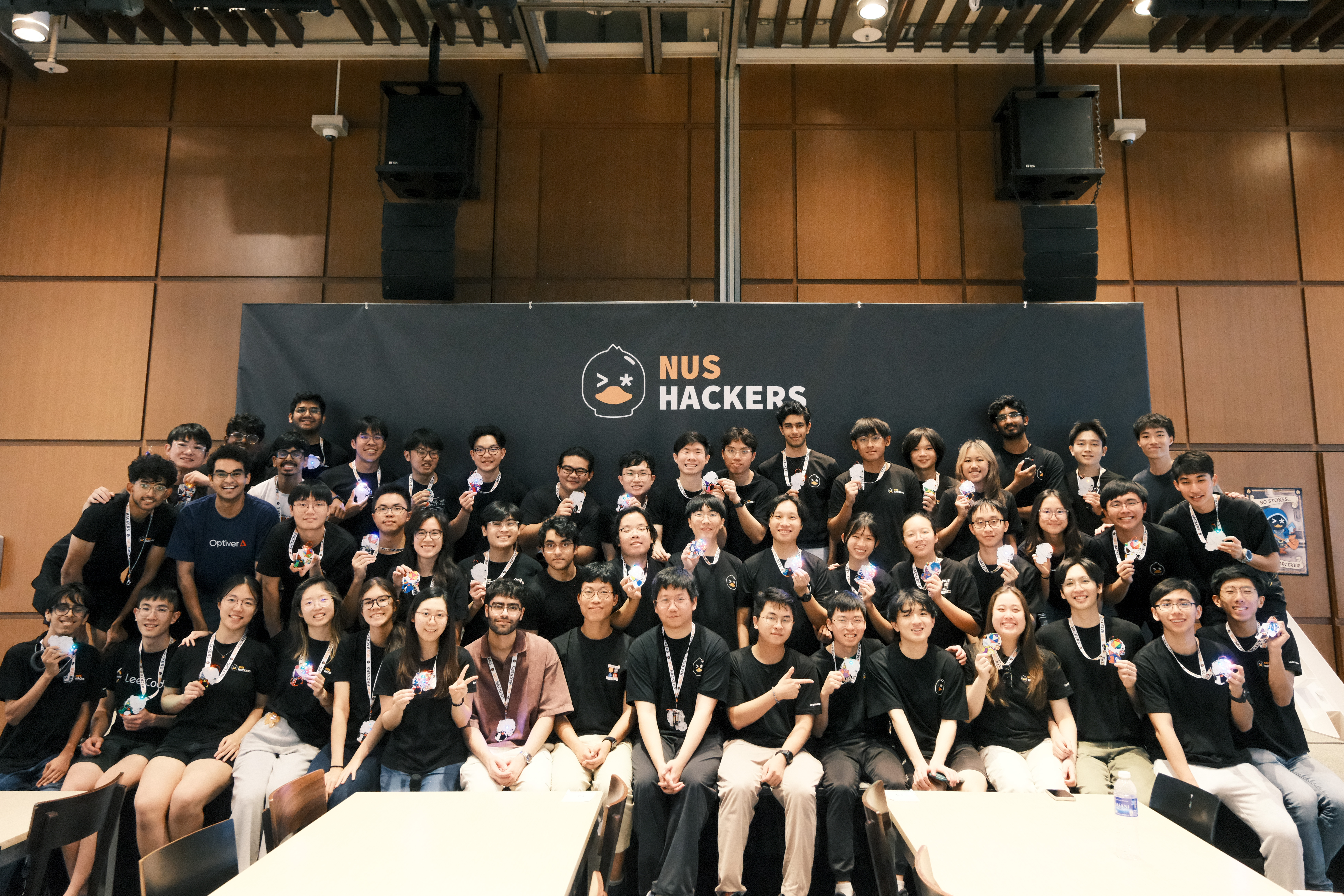
We needed to assemble all 1000 badges. Thanks a lot to NUS Hackers and the various volunteers for their help!
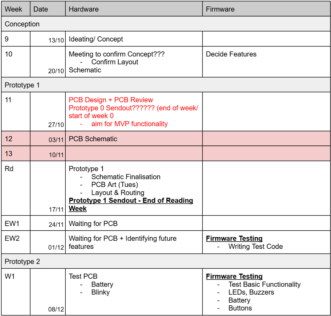
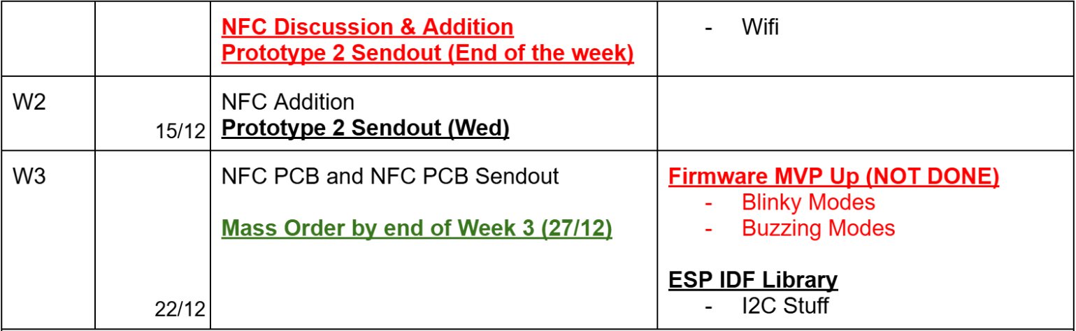
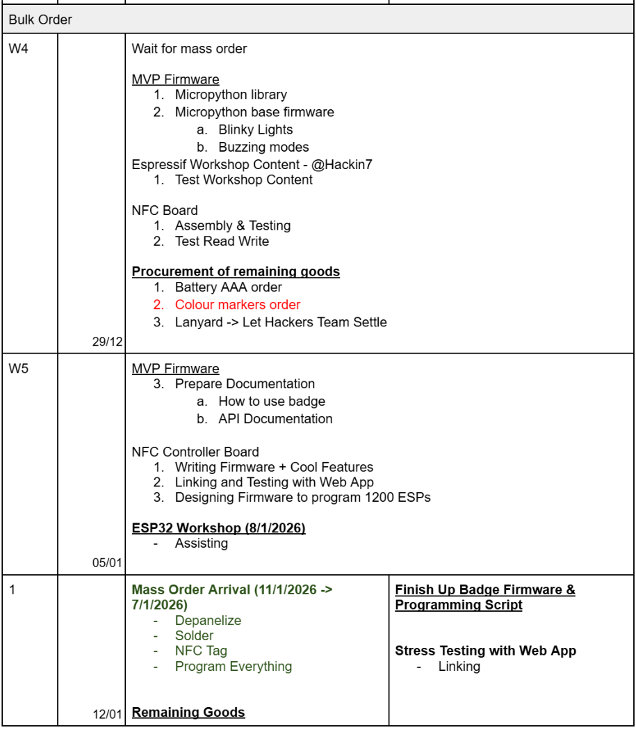
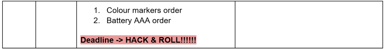
Timeline
Went mostly smooth but with some caveats, most notably the hardware had some stuff
Ordering
We needed to order in these total
- JLCPCB order for 1,149 badges
- ESP32-C3 consignment (thanks Espressif sponsorship!)
- 1,500 PCBs orders, 1,149 assembled
- Batteries from Shopee
- Colour Markers from Popular (thanks Jeya)
- Lanyards from somewhere
- Use lanyards to distinguish people - this worked really well
- Battery holders from Taobao
So PCB wise in total we ordered
- 10 prototype 1s
- 50 prototype 2s (for ESP32 IDF Workshop)
- 1149 Prototype 3s
For a total of 1209 badges
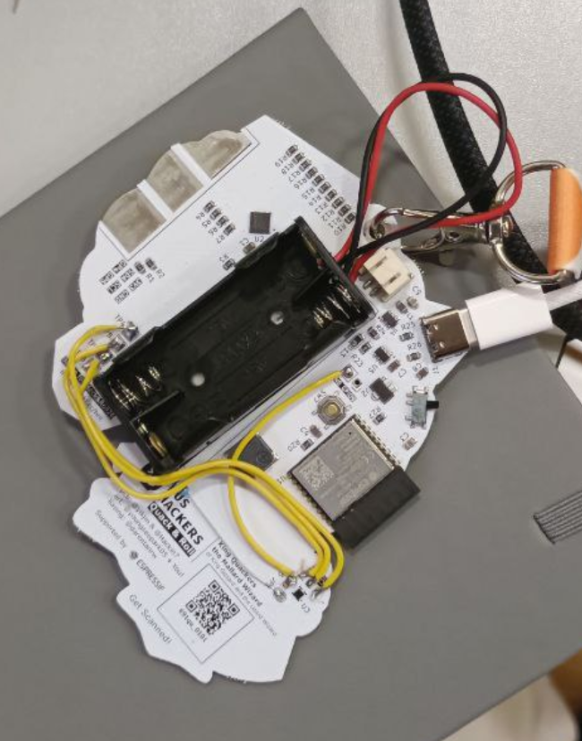
Assembly
The connector for the battery holders did not fit the one on the badge, so we had to strip the battery holder wires and solder them on the badge. Luckily, I put large contact pads in case a situation like this needed to happen.
So we like to liken our assembly process to a CPU Pipeline, and here are the steps done.
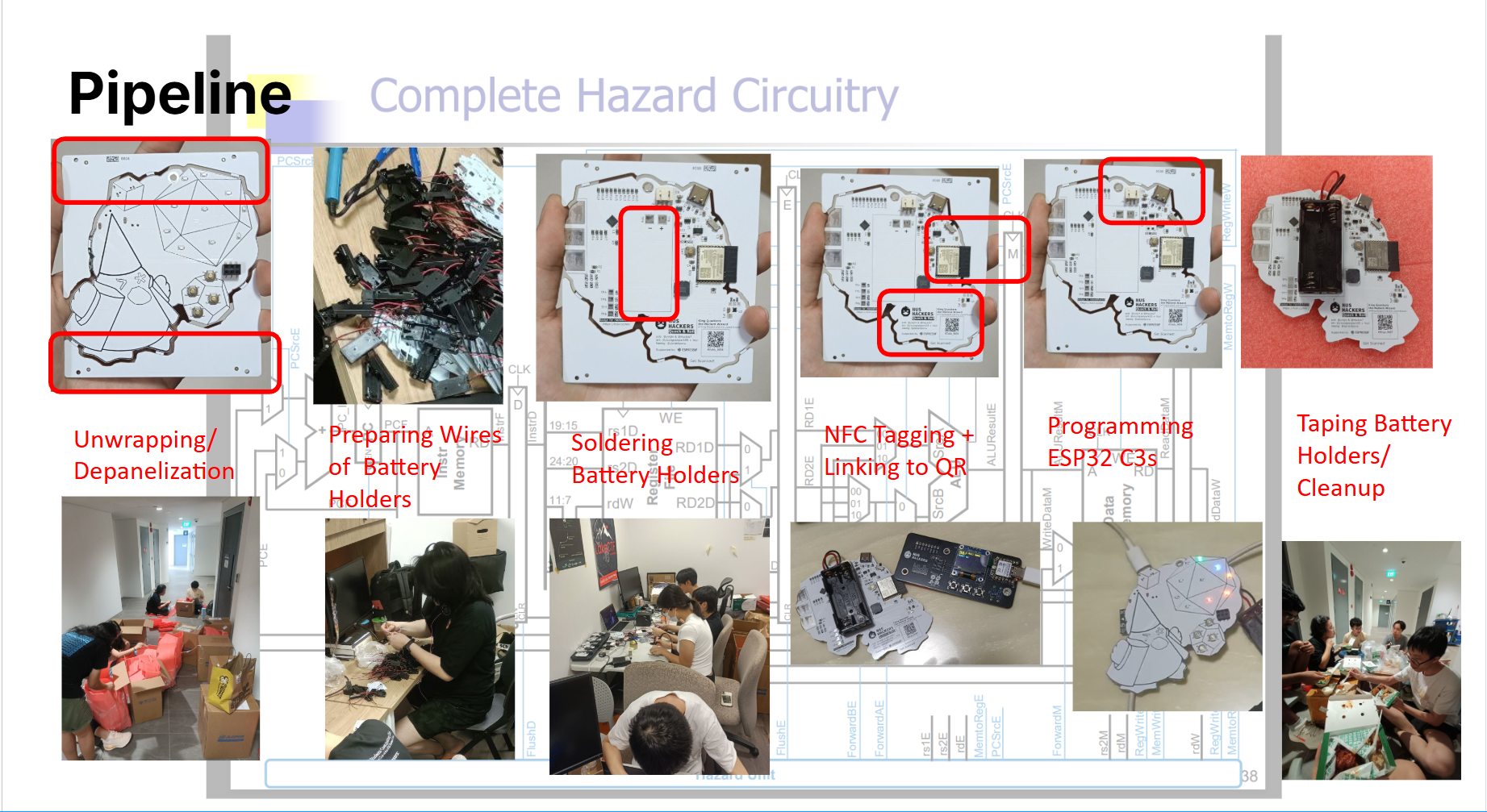
We mainly did it over the week. On the Sunday the week before Hack & Roll, we spent the whole day mainly unwrapping, depanelizing and soldering battery holders. The rest of the steps were done in the evenings/ afternoons the week before Hack & Roll. Since the badge firmware was not done, it was done last, while the other parts were did first.
For NFC Tagging, the setup was mainly ideated by, we had 2 steps
- Scan on a phone
- The phone connects to a webpage hosted by a laptop through ngrok. Ngrok allows for HTTPS which is needed for mobile phone camera
- River came up with the idea lmao
- I remember doing something similar for my Hack & Roll Project too lol
- The phone scans the QR Code on the badge
- It sends a request to a server hosted on the laptop, which then sends it to the NFC tag over serial
- Writes to the nfc tag
This way the QR code and NFC Tag are linked reliably, instead of manually typing it in.
- The phone connects to a webpage hosted by a laptop through ngrok. Ngrok allows for HTTPS which is needed for mobile phone camera
For programming wise, I made a script that autoruns esptool
- Plug in multiple boards at once to a computer
- Auto-detects COM port and programs it + upload MicroPython Files
- Just plug-and-play (1 board about 30s, 3 at a time on 1 computer also 30s)
6. Results at Hack & Roll
Key Events
There were a few key points we were worried about after Assembly & Prepartion:
ESP-IDF Workshop
- Most people could use and program the badges and the LEDs
- There were some library versioning issues in out IO Expander library but that was mostly solved, so not a big issue
- Workshop went quite fell and people made progress.
Hack & Roll
- Registration
- Minor badge issues (which could be fixed)
- NFC eventually used for roughly checking some badges, ensuring they were NFC tagged properly
- No catastrophic failure noted so that's good I think
- Food Collection (Breakfast, Lunch, Dinner)
- Badge Colouring Contest
- Thankfully core team members pushed this through in time, handling prizes mostly went well.
Badge Issues
- Schematic done wrongly for the AW9523 IO expander, such that analog LED Dimming is not supported
- Confusing Switch Modes (but it was easier to implement)
- AAA batteries and the Boost converter was not speced well to support Wireless on the ESP32 without brown out.
NFC Issues
Wifi
School Wifi suddenly failed on the actual Hackathon Day on the ESP32s.
We resorted to Mobile Phone Hotspot but that didn't work too well, since we had to configure and allocate.
Furthermore, iOS hotspots throttle, so we needed to find Android hotspots which do not throttle and work well on the ESP32.
NFC
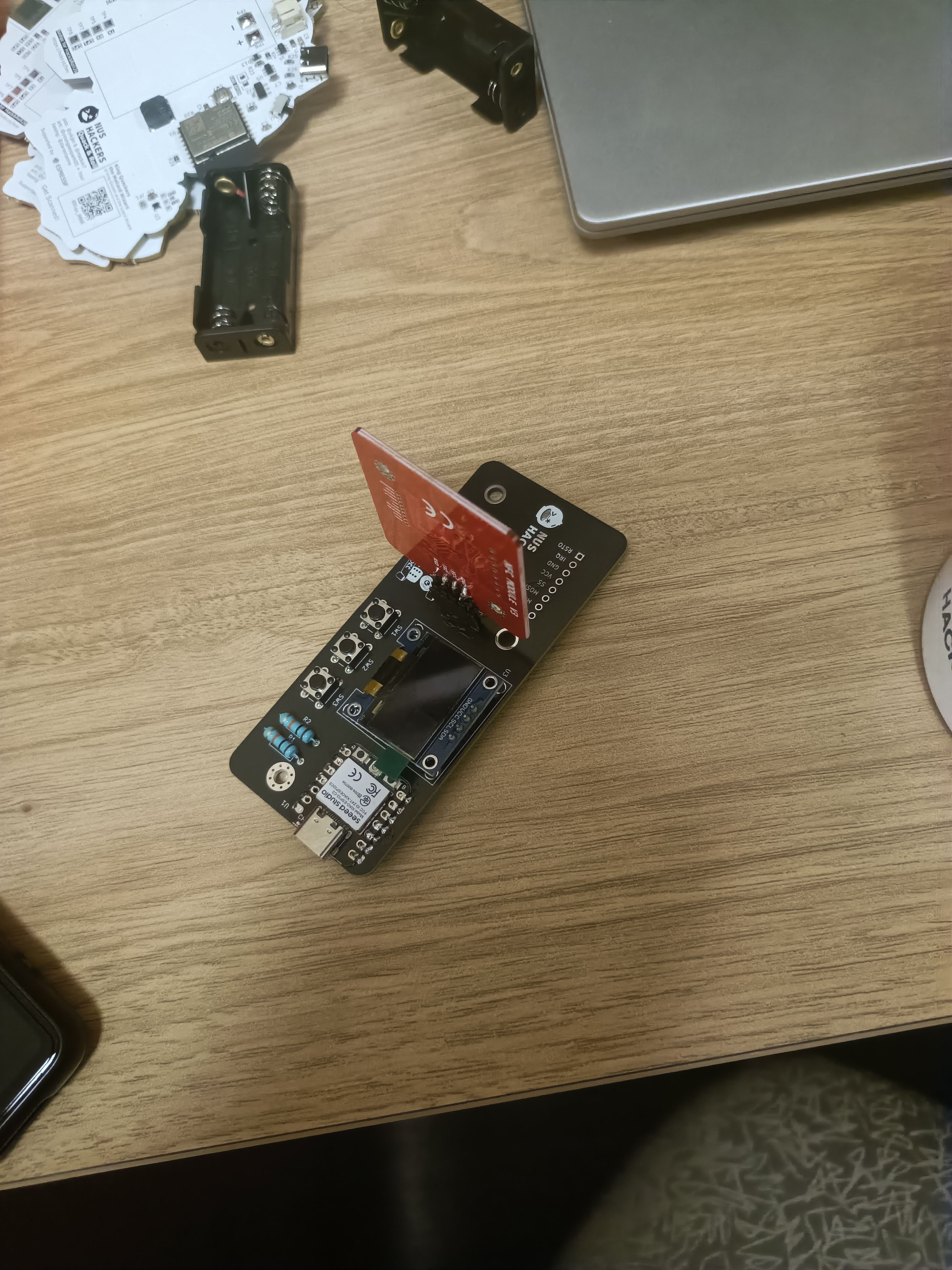
One of the most interesting thing about the NFC Board is that I get to see the effects of RF in action. I personally wanted to learn and do more RF Circuitry, and this was good experience for me.
When the NFC Tagging Board came, initially we assembled it as such. However, we realised that below the NFC board is a Ground Plane, and that affects the Effectiveness of the NFC. This causes us to need to put the NFC tag super close, and in a specific position, for the NFC read write functionality to work.
One Idea I had was to orient the NFC module far away from the ground plane, maybe perpendicular to it. This way the ground plane would not interfere with it. However, being near (kinda) to the Wifi antenna, the Wifi performance suffered instead :( Thankfully, it could still work rather well enough, I just find this as an interesting case of how RF position is super important.
UI/UX
There were also some UI/UX issues on the board:
- No "beep" to let participants identify that their tag is scanned
- Unclear where to tap (some tapped the OLED
- Hotspot situation not ideal (needs hotspot coordination)
Other than that NFC actually seemed cool & tested well in reducing workload (can be manned).
General Hack & Roll Results
Hack & Roll is usually a very successful event, so generally it is easy to say that it is very successful, but I am most interested in metrics involving the engagement with the hardware badge.
| Metric | Number | Notes |
|---|---|---|
| Number of people who received the badges | 809+156+59 = 1024 | |
| Number who coloured their badges | Countless, I keep seeing it in queues | |
| Number of people who participated in the colouring contest | 20+ | |
| Number of teams who did hardware hacks | 22 == 9% of all teams one of highest in Hack & Roll history |
|
| Number of teams who did badge hacks | I never really did a proper count but I saw at least 4 teams | I consider this a great success especially since the badge was a last minute surprise |
| Number of teams who won Hack & Roll with Badge Hacks (got a prize) | 2 |
- wayside -> Using the Badge's ESP Now to connect people together. Tried NFC hacking too- Tap Quack -> Badge Rhythm Game |
| Number of teams who won with a Hardware/ Embedded Hack | 5 |
- wayside- Tap Quack (Quackers Commendation)- Wi Find (Best Hardware Hack)- QuackFor Sizzle- Set to Obliterate Nervous Engineers |
| Scanning of food | Dinner - 200 Breakfast - 125 Lunch - 125 |
Assuming it is about 40% of all food scanned, and without revealing exact numbers. The actual data is likely more |
Given that
- People did engage quite well with the badge
- People won with the badge. Twice.
- The NFC system did work and there is potential
I'll say it was a great success.
Conclusion
Overall this badge was quite successful of a project. In my opinion it wasn't too technically complex, but nevertheless dealing with the ESP32 C3 in a more complex manner (such as WiFi, Bluetooth communication, explaining why my code didn't work in an RTOS fashion and task switching) was quite interesting. I've always wanted an RF project with RF considerations, and through NFC, got me to understand how the design decisions affected real world usage.
On a personal level, the Hack & Roll badge fufills a fair bit of my goals:
- Bring Badge Hacking at scale
- to 1000+ people
- Raise the level of embedded and hardware hacking in Singapore
- Worked on NFC and seeing the real world effects of various design decisions
- From attending Espressif Workshops, to influencing them and helping out with my own hardware,
- working with some of the smartest and most experienced people in the world.
From participating in Hack & Roll 2023 and 2024, volunteering in Hack & Roll 2025, and am now in a position to make decisions to improve and make Hack & Roll 2026 more fun.
Its quite fun.