GreyMecha/Army Execution Deep Dive
GreyMecha/Army Resources
In 2024, I made the GreyCat Badge for GreyCTF 2024. It worked out quite well for what it was supposed to do, and I ended up really liking the final product, and it helped me a lot in my portfolio. However, many of the design decisions were made under constraints. For example, the STM32F103C8T6 chip was used because I had experience in STM32 right before this and I had a schematic. I used the GreyCat as a design as it was simple and easy to work from.
For AY2425, GreyHats had a rejuvenated team and organisation structure. We had new hardware blood with greater experience manufacturing and designing for scale. We know this time that people care about our badges, and people are excited to see them, and so
I haven't exactly played around with many other hardware badges myself. What I do know is that many other Cybersecurity events are starting to have hardware components. We had the GovTech C01N, SINCON badges since 2023, STANDCON badges (this year's badge is quite interesting), Cyberthon badge, Off By One etc. However, being a student led club, and furthermore making this in a CTF context too, this gave us a lot of freedom in exploring how far we can push the limits of hardware.
I wanted to make the best possible hardware badge I possibly could, with whatever help I could.
This blog post is going to be an extensive writeup of how the GreyMecha/Army badge was ideated/ conceptualised, and executed. This year there were a lot of improvements on how the badge was made, and I thought it'll be good to log them down for future generations of badge makers
Ideation
Before we started doing any real work, we needed to figure out what our badge was even supposed to be. Last year, I had a very simple idea right from the start, which was GreyCat shaped STM32 bluepill. And the initial idea was to explore the hardware peripherals of the STM32 in the challenges (which were done somewhat successfully).
A fair bit of time was spent brainstorming badge ideas. There are 2 parts to this, Electronics, and Artwork
Electronics
For a hardware badge, we wanted to do something new. More specifically, something new in Singapore.
There are many different badges and stuff. However, most of them implemented a single microcontroller, sometimes the ESP32, other times a cheaper microcontroller. Some of them implemented 2 microcontroller, most notably the Off-By-One 2024 Octopus badge with an ESP32 <-> ATMega328, but also the STANDCON 2025 badge with an RP2040 <-> STM32.
Overseas, in ECSC, BluSG implemented the Pizza Hardware Challenge. It has a Pizza Slice with an RP2040 to interface with the main pizza, which has a Blu5 chip. The Blu5 chip has an FPGA and a STM32 on a chip.
Having done modules such as EE2026 Digital Design, EE4415 Integrated Digital Design, and EE4218 Embedded Hardware System Design, I've had a lot of exposure with Verilog and Digital Logic, and I've made a few challenges on that. So I thought, why not make a badge with an FPGA?
However, the badge with just an FPGA alone would be quite difficult to make + it wouldn't be much fun. So I decided early on that an MCU was needed to interface with the FPGA. Based on leyew's experience with the RP2040 for Keyboard PCBs, + the Programmable IO features which would ideally allow us to interface with the FPGA at high speeds, we were going to go with the RP2040. I then decided to use the RP2350 instead because it was newer and hopefully more fun, able to explore the SHA256 accelerator and other security features if we had time.
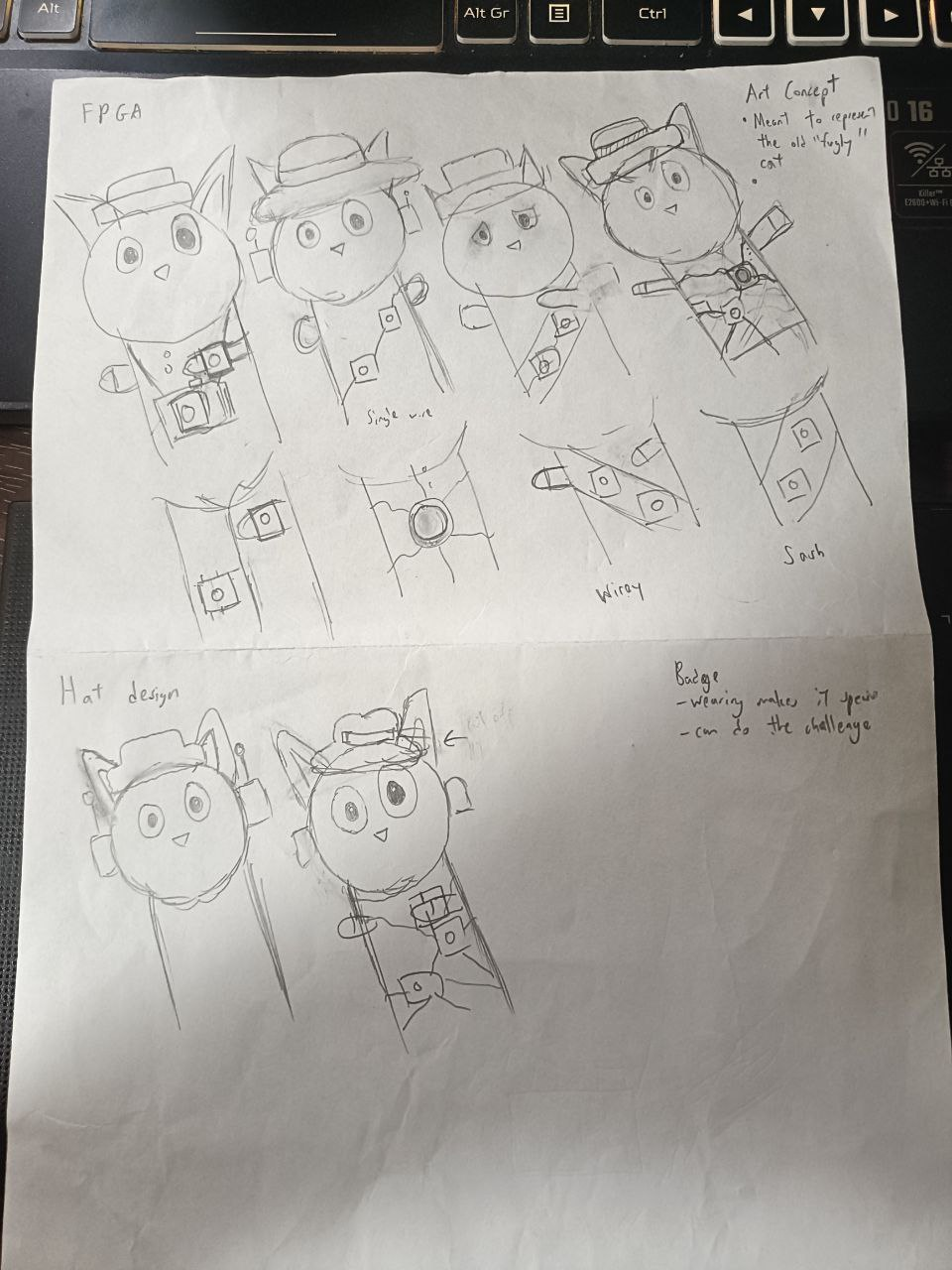
Initial Art Concept
After last year's design, Ideating a new badge design was a challenge. There were many ideas but generally, most of what I've seen are these
| Badge | Description | Examples | Image Example |
|---|---|---|---|
| Character based badges | These are badges which are a certain character. | Some good examples include the Off-By-One badges, last year's GreyCat badge, DEFCON badge, and more. | 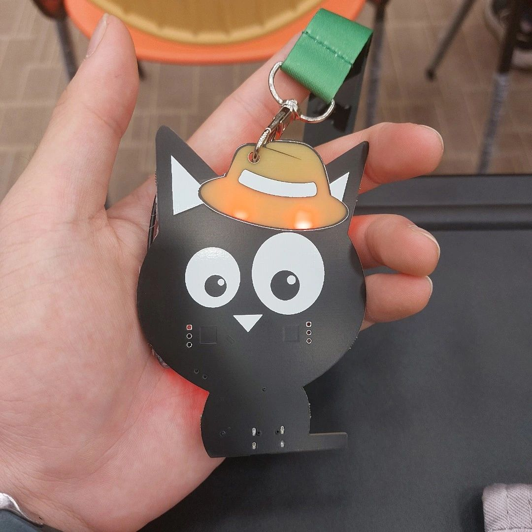 |
| Item badges | Similar to 1 but they represent an item/ architecture instead of a character. |
Some good examples include the SINCON badges, the STANDCON 2025 badge |  |
| Gameboy like badges | These are badges not really based on a character, and might not even have much other art. They are designed to be seen as a technical piece of equipment, and so their art is designed to reflect that. Their controls are laid out like a mini gameboy. |
Some examples include the hackaday badges, The X-CTF badge, and more. | 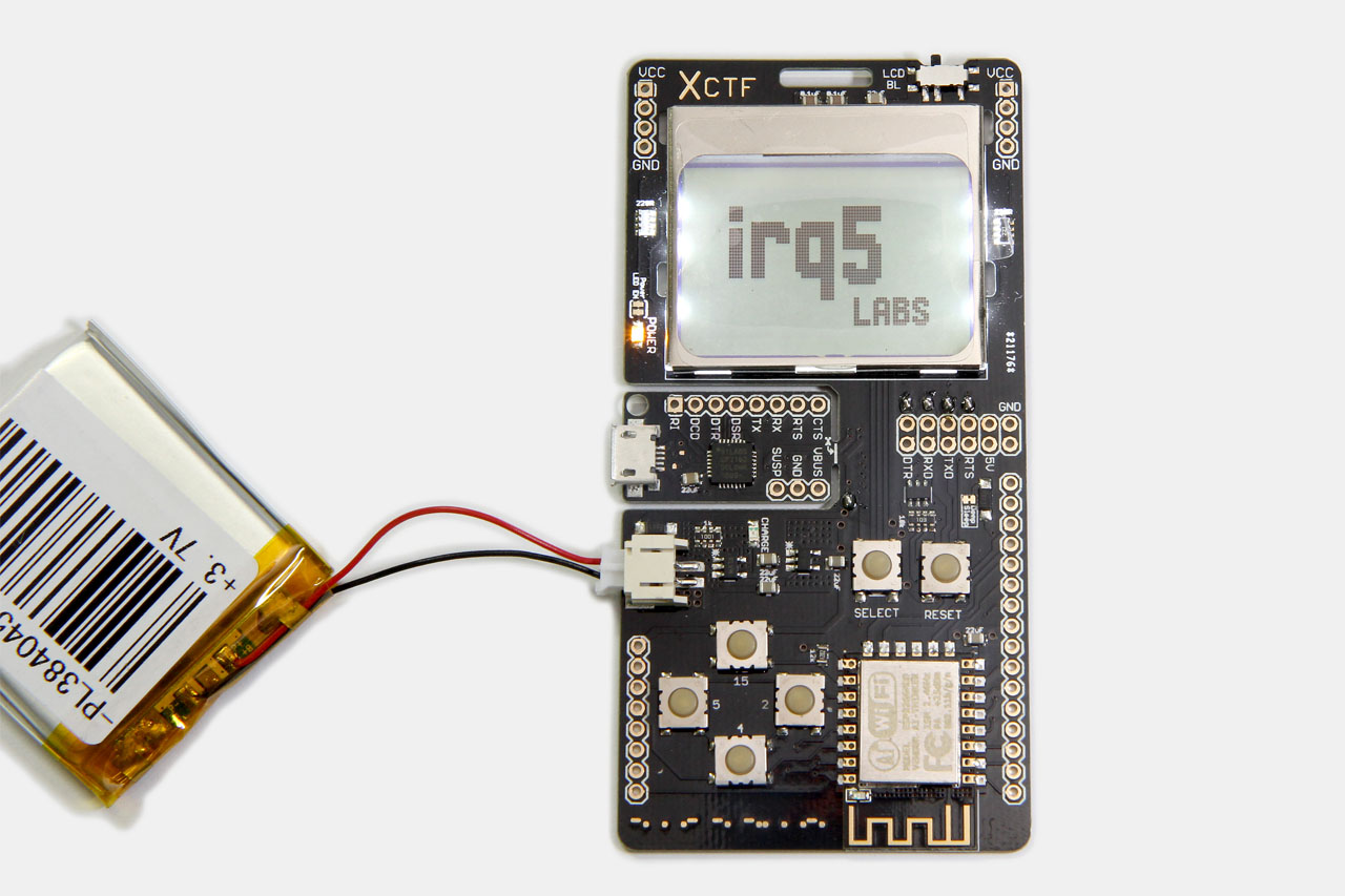 |
One of my biggest inspiration of badges were the Hackaday Supercon Badges, they were very very technical. More specifically, the Vectorscope badge stood out to me because it was designed for analog usage. Another inspiration were shows like Godzilla, or basically any big terrorising object thing.
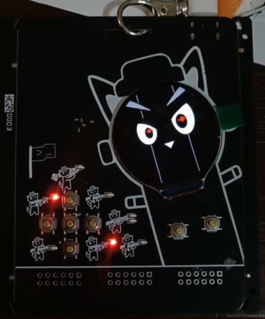
I've also had experience working with GC9A01 OLEDs, using them for the maibadge project. Similar to the maibadge idea, I thought what if, I could use the screen as the cat's face?
However, that was still too small, so I had an idea of adding a mini cat army with LEDs. And afterwards, we had space to add some game controls.
Overall
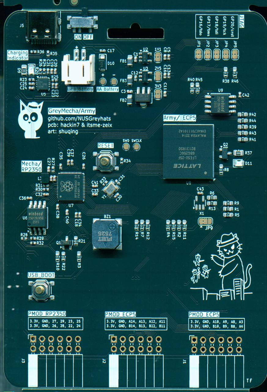
What really turned out quite interesting especially, is how these 2 interlinked with each other. The badge is intentionally designed such that the "Mecha" (OLED, Core button, Wrist Button) is controlled by the RP2350, which is this bigger and more complex computer. The "Army" is controlled by the FPGA, for parallel processing.
The design and artwork also lines up with how we as NUS Greyhats changed over the past year. We moved away from having a few core personnel tanking all the admin and logistics of our events (Mecha), to growing our team such that the workload is better spread out (Army). Even the artwork lines up, as we transitioned from the old cat design with the Mecha to shuqing's new cat design with the Army.
Combining
- The badge layout and RPi Pico of the Vectorscope Badge
- The Architecture of the ECSC Pizza
- The Game Boy controls of the X-CTF badge
- The cat of GreyCat Badge
- The OLED Face of maibadge/Eyes idea of Off-By-One Badge
Gives you the new badge, GreyMecha/Army. It both takes inspiration from our past badges and from neighboring badges to create something quite unique.
Hardware
FPGA Design
Selection
So as for Implementing the FPGA on a Physical Hardware Design, the first most important thing is to source the chip we wanted to use. We were initially thinking of an ice40 8K FPGA. However, after more research, we found the LFE5U_25F_6BGA256C chip. This chip was 5USD, had the most stock on LCSC/ JLCPCB (where we were planning prototyping/production runs with), and had a significant amount of LUTs, 25K LUT4s. It's very similar to the Basys3 board, though with worse LUTs.
Component Analysis Did
iCE40LP8K-CM81
- https://jlcpcb.com/partdetail/Lattice-ICE40LP8KCM81/C1521979
- $8.81/pc
- https://www.digikey.com/en/products/detail/lattice-semiconductor-corporation/ICE40LP8K-CM81/3877704
- $11.55/pc
LFE5U-25F
- $11.55/pc
- https://jlcpcb.com/partdetail/Lattice-LFE5U_25F6BG256I/C5272996
- C5272996 - https://www.mouser.sg/ProductDetail/Lattice/LFE5U-25F-6BG256I?qs=w%2Fv1CP2dgqpEY7AiGO6aWg%3D%3D
- $31.25/pc
AGM Microelectronics AG16KL144A
- $31.25/pc
- https://www.lcsc.com/product-detail/Programmable-Logic-Device-CPLDs-FPGAs_AGM-Microelectronics-AG16KL144A_C41397170.html
Reference
I dug out various FPGA Design References, more specifically on ECP5. The ECP5 is well documented and reverse engineered online,
https://github.com/tinyfpga/TinyFPGA-BX?tab=readme-ov-file
https://github.com/apfaudio/soldiercrab
https://github.com/Spritetm/hadbadge2019_fpgasoc/
We referenced various ECP5 PCBs, most notably basic-ecp5-pcb for the reference schematic.
For the pinout, we used the relevant github repo
However, on our production run, I miswired the Flash schematic, swapping DIN and DO. This wasn't an issue for our badge due to the ability to program via JTAG from the RP2350, but is nonetheless a bug. (thanks a lot to sayo for figuring it out, though we only had time to find it after the CTF)
We had considerations over power. Looking at the board, it didn't seem to consume so much power, so we eventually moved over to LDOs from switching regulators on basic-ecp5-pcbs our 1st prototypes for ease of wiring, and more importantly, for stable power in the event of expansion (hint: analog?)
A huge portion of the badge relied on if the FPGA could work and if there were issues with BGA routing, so when the FPGA on our 1st prototype worked it was a huge win. This allowed us to develop our firmware and hardware iterations in parallel.
Structure
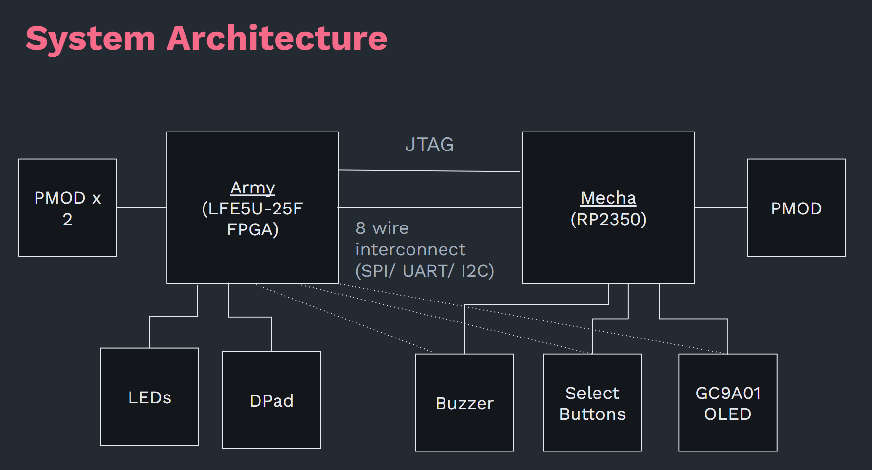
I designed the architecture as such. I offloaded the LEDs and DPad Button IO to the FPGA mainly to make up for the RP2350's lack of I/O Pins. Since the FPGA had so much I/O, I decided to connect all the capabilities to the FPGA. This theoretically means that with a decent RTL writer, you can control the whole badge with the FPGA alone. However, I didn't have time to test and debug that, but would be nice if other people did.
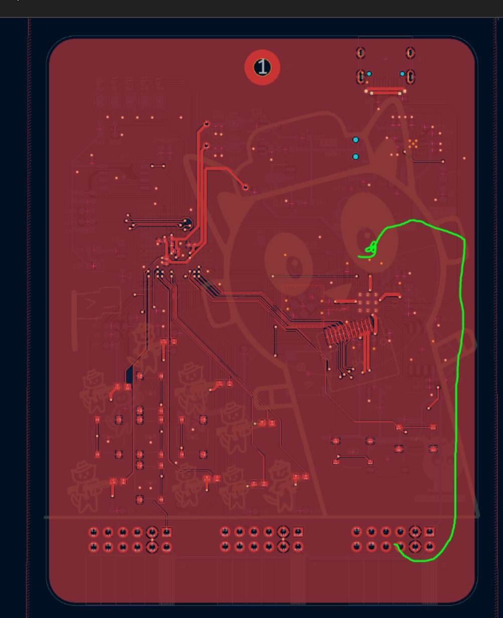
PCB Routing
The PCB Routing for GreyMecha/Army is more complex than for GreyCat2K24. The main consideration for GreyCat2K24 is to fit everything on effectively 1 layer, so that traces are not visible on the front side (where the cat imagery is). GPIO Pins were chosen based on the proximity to the component, and then everything else was routed out in a star fashion. Honestly the bulk of that routing was done in 2-3 days, so it wasn't too hard.
On playing around with the Off-By-One 2024 badge, I realised that traces at the front were not such an important deal as I thought they would be.
This year's GreyMecha/Army had more complex considerations to think about. There were a lot more components, power sources and design considerations. Not to mention routing BGA was a challenge.
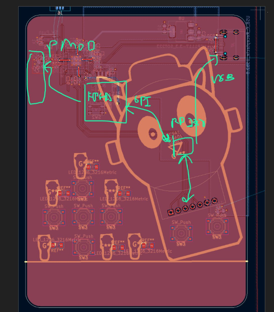
Board & Component Placement
Firstly, I took a gamble and used a 2 layer PCB for the FPGA. Most designs typically used 4 layer boards, where some layers were dedicated fully for ground planes. In a high speed FPGA design with various peripherals, it would make sense to use the middle layers to route out important signals, as well as to do length tuning. However, we did not need those requirements yet (we don't even need ddr3 memory). Though the ground plane would help for signal integrity, I decided to try my luck without it, and the FPGA worked well enough for it. 2 layer boards were cheaper and helped us order cheaper (a little bit) and prototype faster.
Furthermore, we decided on a simple rectangle shape for our badge. While this does make it less aesthetically pleasing in some ways, it makes it easier to do component placing and routing. Considering the complexity of our board, I think it worked out well enough.
One issue I found out AFTER the CTF was the proximity of the lanyard to the power regulators. I only knew about this after the CTF, when watching some badge talks on the DEFCON 30 badge. I have personally never experienced a badge breaking before, but on the summit feedback form, I think one person said their badge broke due to this (oops). If that person is reading this article, lmk and I'll try to fix it!
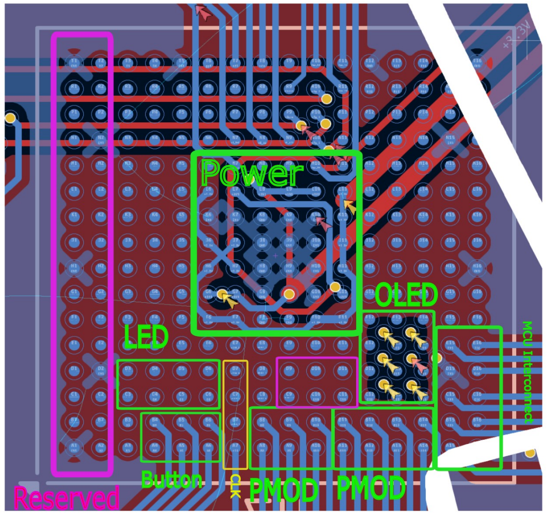
BGA Routing
For BGA routing, I used phils labs' guide. I did a dogbone method, routing out each ball at a 45 degree angle, and then putting them through vias.
I segmented off sections of the FPGA for specific things, like LEDs, OLED, Buttons, Power, and then routed from there. For the pinout, we used https://github.com/devbisme/KiCad-Schematic-Symbol-Libraries/tree/master/lattice
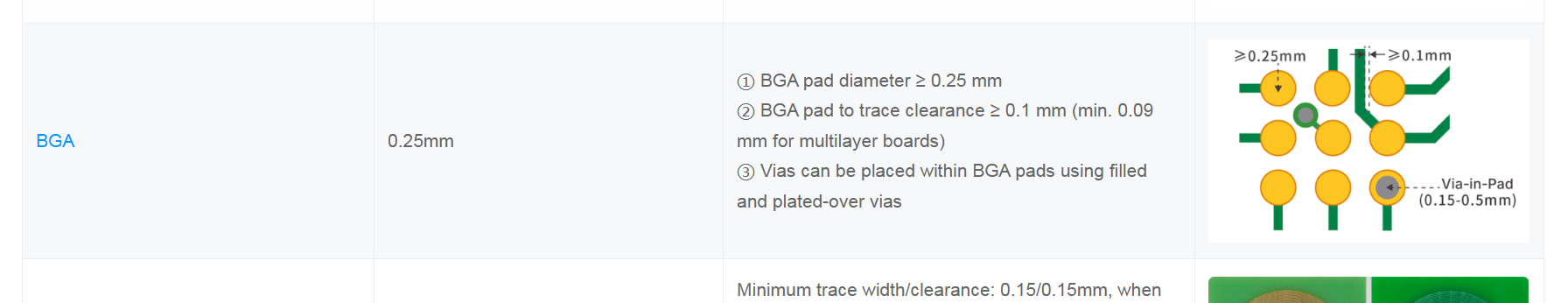
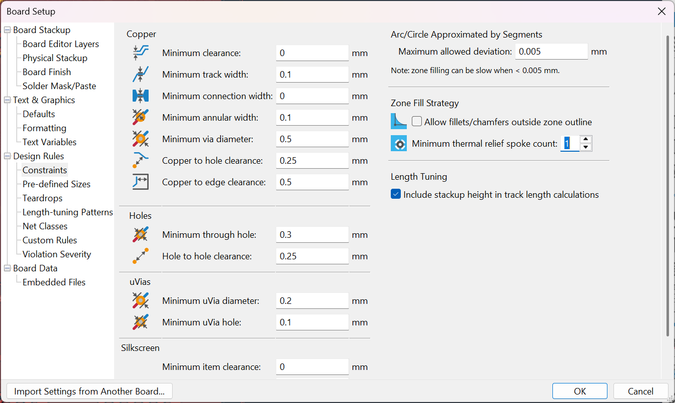
Configuring the JLCPCB DRC settings took a while, but the concept is to reduce the annular ring on the vias, as well as to make the traces thin but still fitting JLC PCB Constraints.
https://jlcpcb.com/capabilities/pcb-capabilities
https://github.com/labtroll/KiCad-DesignRules?tab=readme-ov-file
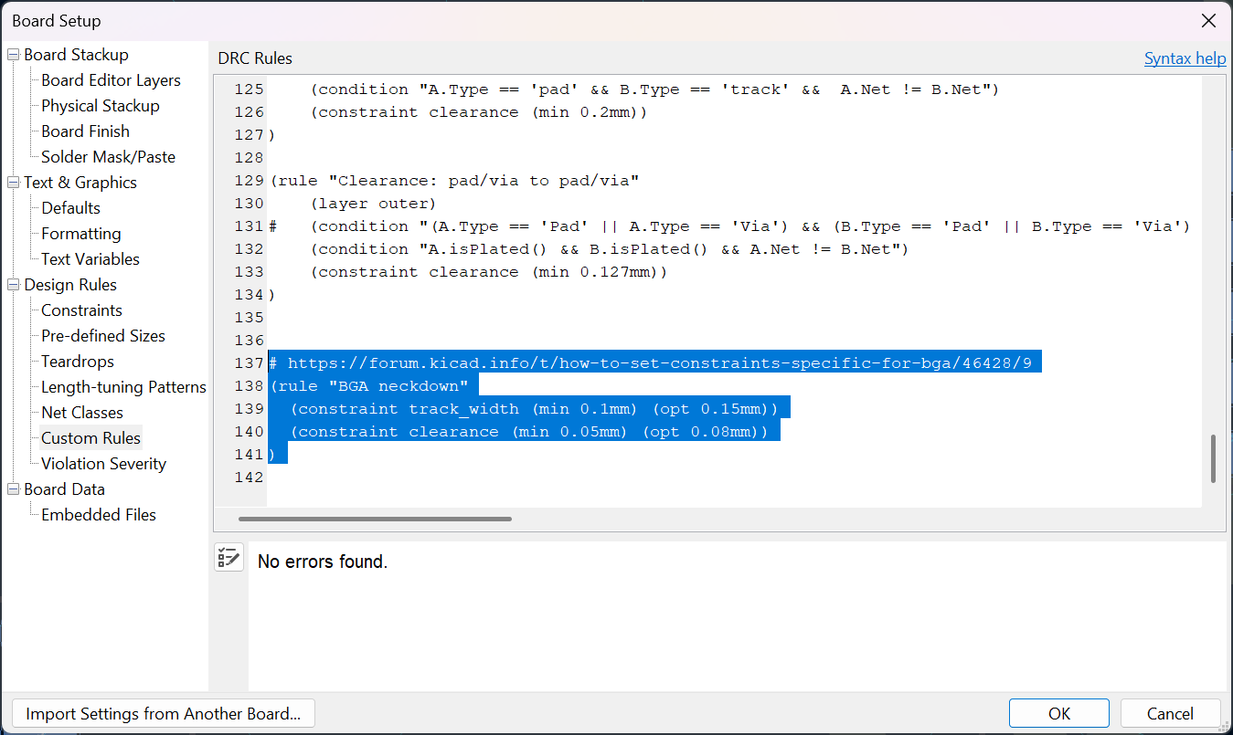
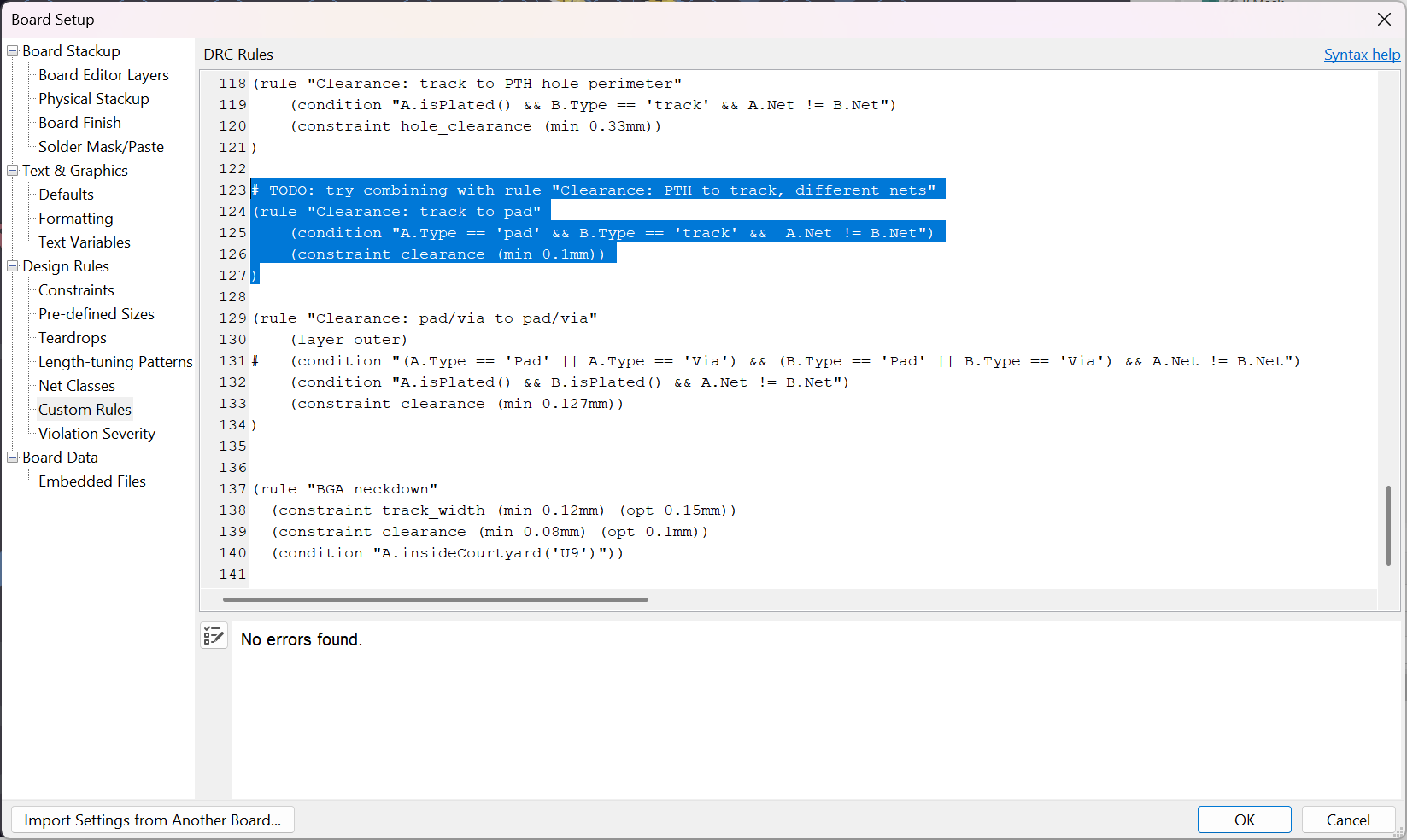
Theres some clearance thing that needs to be changed eh
JLC might make some complains but generally BGA routing works on JLC
We had to make some sacrifices, most notably routing ADC and PMOD pins through vias, but as they were not critical and mainly there for expandability, we decided it was ok
Side Note - Secret Development Kit
I took Prototype 2's PCB design files, whacked some whacky graphics, made some adjustments, and turned it into a CTF challenge... while I was away in Switzerland for LakeCTF/ Travel. It was a simple fun challenge.
The idea behind secret development kit is to
- Act as a teaser to GreyMecha/Army - I think it would be nice if the participants can see a piece of the badge in qualifiers and see how it links up during finals
- Test PCB knowledge. Silkscreen was put to intentionally cover copper areas, but in production, they would be uncovered, so I thought it would be kinda interesting to explore that.
More information on the solve is here:
https://github.com/NUSGreyhats/greyctf25-challs/tree/master/quals/misc/secret-development-kit
Art
Initial Concept
I came up with the initial design and concept. Here are some concept art
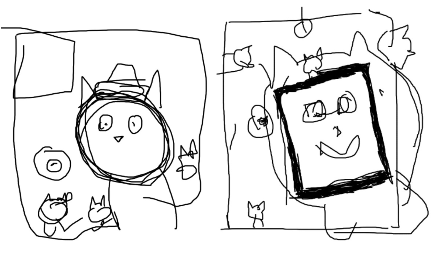
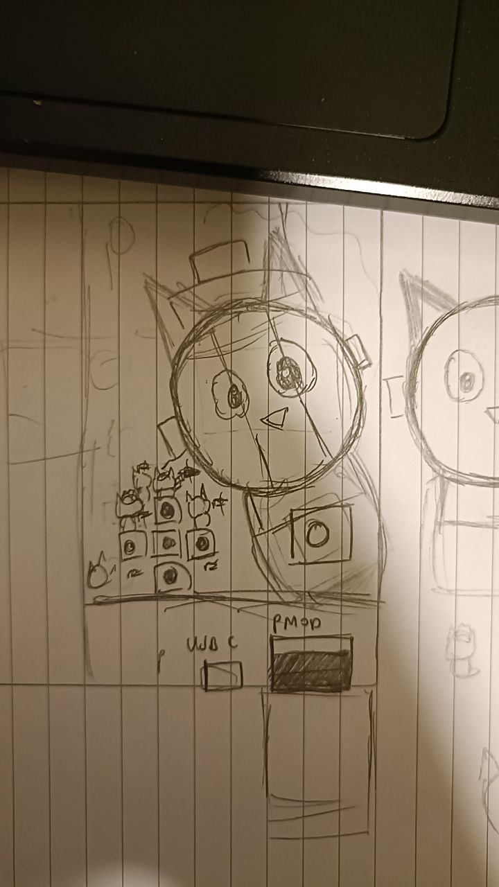
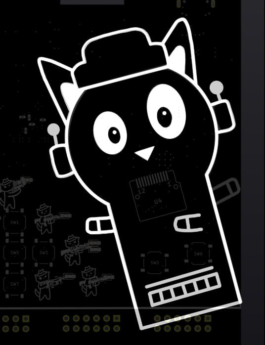
New Artwork
However, eventually I wanted to improve the design, and so I asked shuqing for help. She designed the new cats holding the weapons (from the Security Armed Forces).


Button Positioning
Button Positioning was a consideration, the button positioning of our 2nd prototype didn't exactly look the best. With shuqing's designs, I tried to ideate something that would work, by shifting around the positioning.
shuqing's ideas
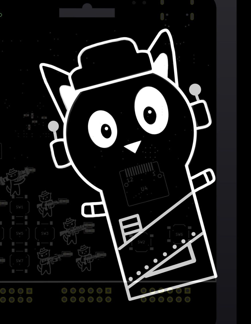
My ideas - I curved the lines and made it look more hand drawn
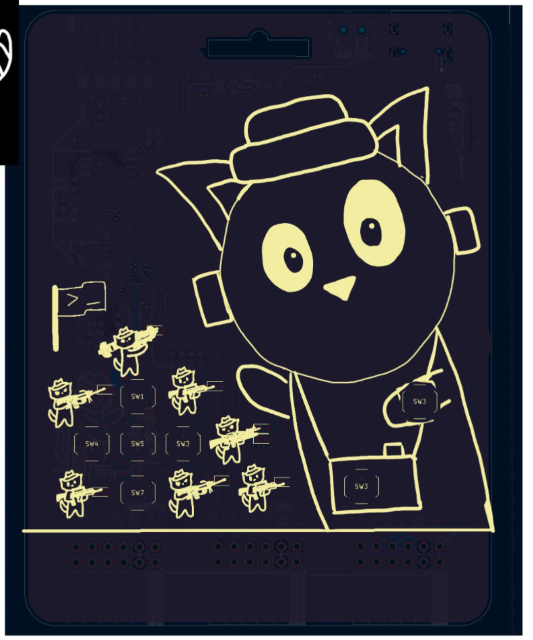
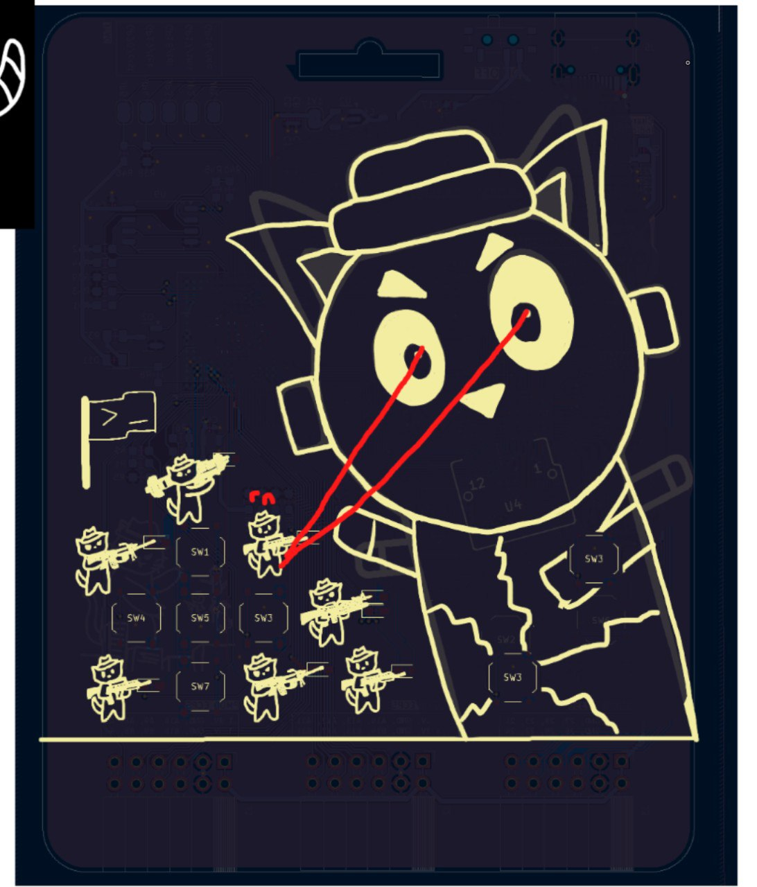
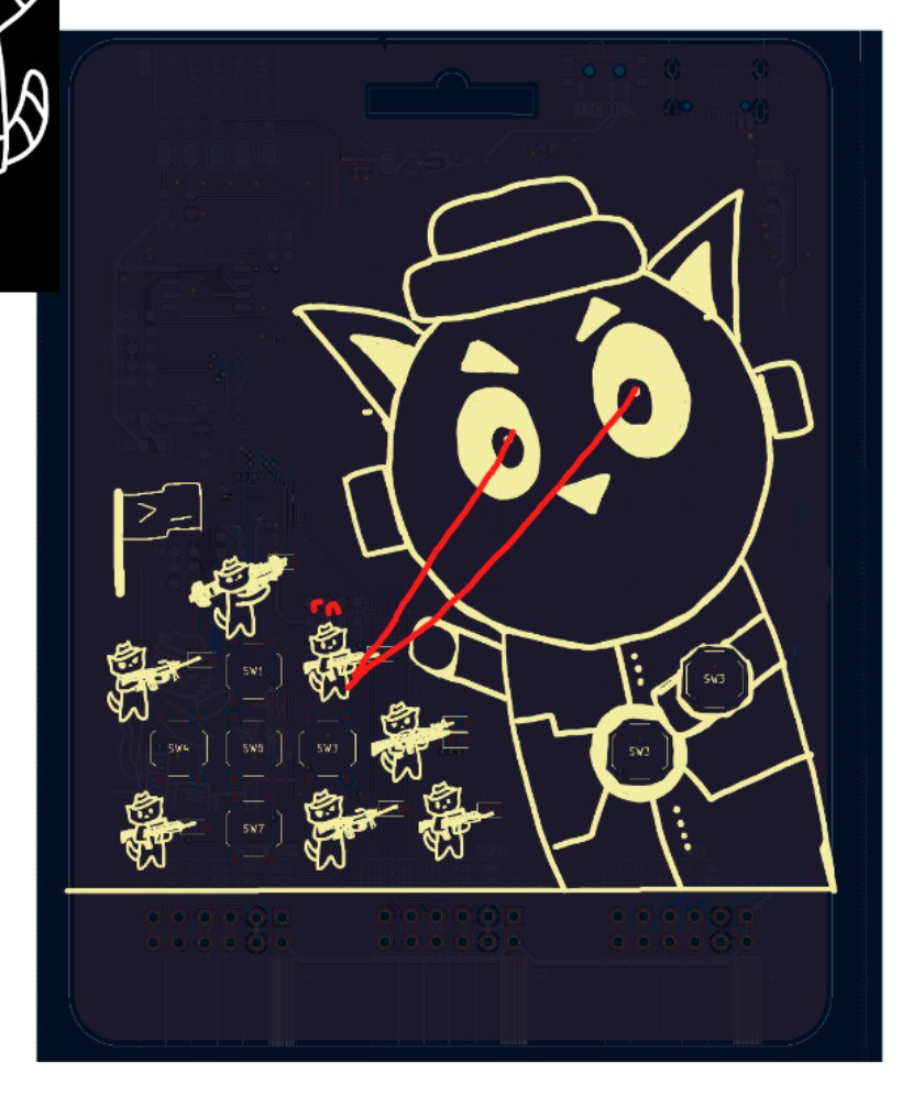
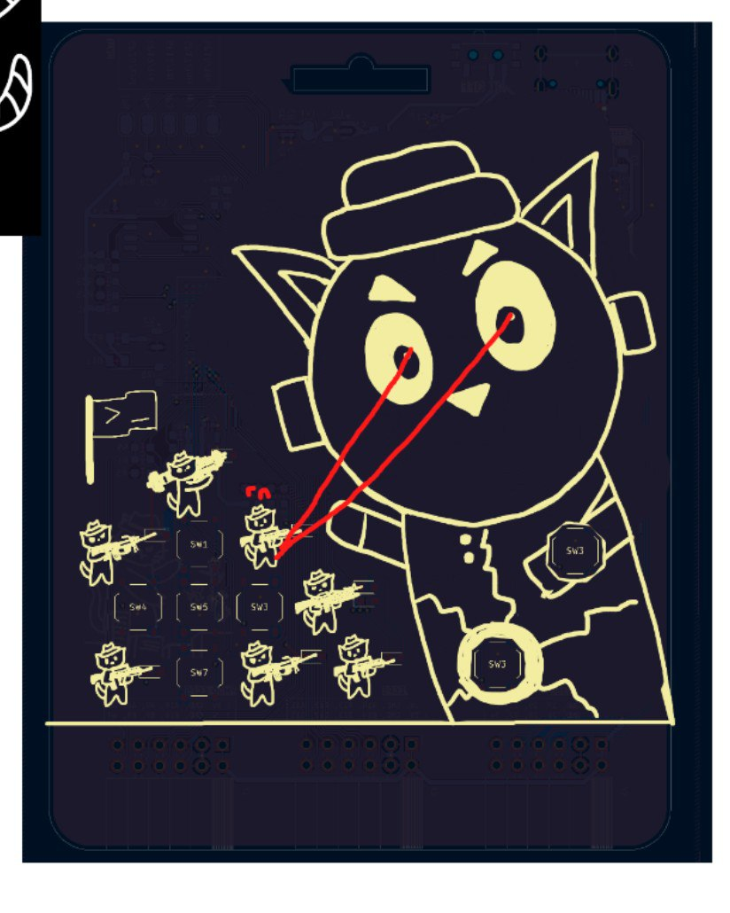

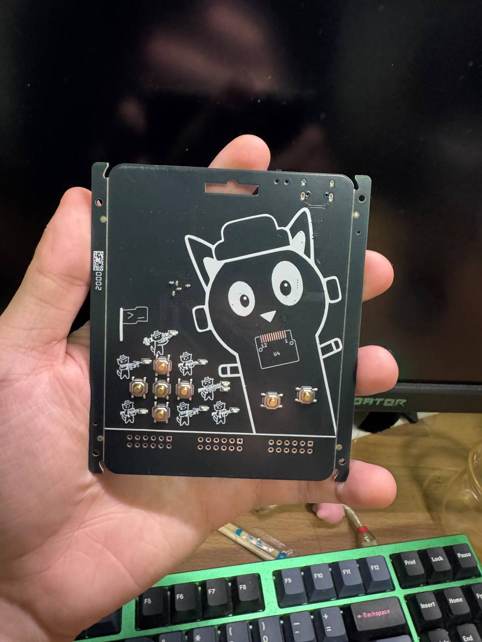
On production, I realised I didn't scale the face correctly to the screen, such that the silkscreen is larger than the OLED screen. I decided to keep it though, as I thought it would add a 3D feel to the head, kind of like facing towards the army.

Production
We stuck with 3 prototypes for GreyMecha/Army before the final production run. We used JLC for our prototype runs due to ease of PCBA. We went with another producer for the final run due to stock issues.
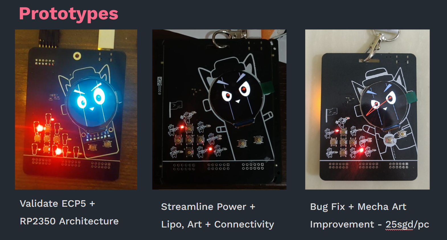
We probably could have kept the costs down by reducing unnecessary components and optimising more, but a 25 SGD FPGA is quite decent I think.
If we had more time, we could aim to pre order components from JLC to reduce costs further.
Firmware
RP2350 Structure
From the start, I knew I wanted circuitpython. Having used micropython for maibadge, and compared it with Circuitpython, Circuitpython has more tools for animations and graphics, usb hid, and more useful libraries in general.
I designed a rough application layer (inspired by my experience on maibadge) where each application is a function, that takes in the relevant hardware peripherals. I was thinking if this much effort needed to be put in to the badge, but considering what people other than myself have done, I think it paid off. It allowed for people to easily customise the badge however they want.
In an effort to obfuscate some code, we compiled and embedded some micropython modules into the main firmware. However, we knew this was a temporary stopgap and not a solution, but the idea is to prevent the challenges from being fully ChatGPTable.
The tools I used for development were Thonny (for the REPL) and cpsync which syncs the filesystem from the badge to a local folder on your computer. I just committed the libraries to the Github Repo, but you could probably script something with circup to download the libraries as required. A useful link i referred to is https://johnwargo.com/posts/2023/synchronizing-circuitpython-files/ .
There were some problems fiddling with the Programmable IO, I'll leave leyew to talk about it in his blog post.
JTAG Programming through the RP2350
We knew it was possible on the RP2040 with the use of DirtyJTAG, a program which uses the PIO functionality to simulate JTAG. We also knew it was possible with the ESP32 on the solidercrab ECP5 boards, the ESP32 uploads the bit stream to the ECP5 through SPI and JTAG in Micropython. The relevant link is at https://www.hackster.io/news/the-esp32-is-the-chip-that-keeps-on-giving-this-time-as-a-wi-fi-jtag-programmer-for-the-ecp5-1319c7570c01
However, we wanted it done in the RP2350, and in Circuitpython, as these were used for our badges. What we ended up doing was porting the ESP32 code. As we didn't reserve an SPI Bus for JTAG (1 was for the screen, 1 was for general usage), we had to use SoftSPI. It takes quite a fair bit longer to upload the bitstream, but at least the bitstream is uploaded. Someone could ideally write a more efficient JTAG Driver for the RP2350, but for the sake of fast Development, this works for now.
Verilog
Yosys toolchain
Finding a good tutorial for this took a while of digging through YouTube Videos and Resources, but we eventually settled on a few.
- https://youtu.be/Xvt3yhEtiHk?si=UQabMVRsyHiSjb13&t=1049
- Someone made his own ECP5 PCB and the setup of the project is in the video. The relevant commands/ makefile is also in this video
- Pinout CSV - https://www.latticesemi.com/Products/FPGAandCPLD/ECP5
- https://github.com/BrunoLevy/learn-fpga/blob/master/FemtoRV/TUTORIALS/toolchain.md
- Constraints File?
- https://github.com/YosysHQ/prjtrellis/blob/master/examples/ecp5_evn/ecp5evn.lpf
- A good reference of what a constraints file should be like
- Get pinout
Pinout naming example - The +- shouldnt matter
What was interesting to know is that the pinout mapping maps directly to the pin labels on the chip package. This made it much easier for locating pinouts instead of having to reference yet another chip pinout diagram, we could just look at the row and the column.
JTAG Programming using DirtyJTAG
I had an extra Raspberry Pi Pico which I used to initially debug the FPGA
Just download install here
https://github.com/phdussud/pico-dirtyJtag/releases/tag/V1.06
Installing openFPGALoader to test
https://trabucayre.github.io/openFPGALoader/guide/install.html
You can run the openFPGA Loader on WSL, and use usbipd to bridge the USB device to WSL
The commands to install the relevant tools are as such
sudo apt install openFPGALoader
sudo apt install yosys
sudo apt install nextpnr-ecp5
sudo apt install fpga-trellis
Wait a min
┌──(hacker㉿HackerbookAce)-[~]
└─$ sudo openFPGALoader --cable dirtyJtag --detect
empty
Jtag frequency : requested 6000000Hz -> real 6000000Hz
JTAG init failed with: Unknown device with IDCODE: 0xffffc003 (manufacturer: 0x001 (), part: 0x7f vers: 0xf

┌──(hacker㉿HackerbookAce)-[~]
└─$
The above output generally shows a connection issue, after fixing the connection, this command worked for flashing
sudo openFPGALoader --cable dirtyJtag test.bit
Meanwhile our flash not working too well, but thats another discussion
┌──(hacker㉿HackerbookAce)-[~/fpgaing/shooting]
└─$ sudo openFPGALoader -f --cable dirtyJtag test.bit
empty
write to flash
Jtag frequency : requested 6000000Hz -> real 6000000Hz
Open file DONE
Parse file b3bdffff
DONE
Enable configuration: DONE
SRAM erase: DONE
Detail:
Jedec ID          : 18
memory type       : 04
memory capacity   : 98
flash chip unknown: use
Internal Oscillator
Our initial idea was to include an external oscillator with every badge. However, on looking into the flashing modes, I realised that the FPGA has an internal oscillator that we can actually expose and use it to do combinational logic
There isn't really extensive documentation online but you can check the ECP5 SysCLOCK and PLL Datasheet, at https://www.latticesemi.com/view_document?document_id=50465. You can then set the divider appropriately to get a roughly desired clock frequency.
/// Internal Configuration ///////////////////////////////////////////
wire clk_int;        // Internal OSCILLATOR clock
defparam OSCI1.DIV = "3"; // Info: Max frequency for clock '$glbnet$clk': 162.00 MHz (PASS at 103.34 MHz)
OSCG OSCI1 (.OSC(clk_int));
I haven't really experienced significant issues with the internal clock (though an external one is likely more reliable), it works on 460800 baud, so I think it should be fine for casual use. I haven't really stress tested it for faster use.
The ECP5 also has a PLL which we can use to output higher clock frequencies from the input frequency (of the external oscillator) https://projectf.io/posts/ecp5-fpga-clock/ . However, as we decided not to use external oscillators (if we did we had to hand solder), we didnt test this much. There are more primitives and fancy features of the chip documented at https://github.com/YosysHQ/nextpnr/blob/master/ecp5/docs/primitives.md.
Using it with Yosys gave me Timing Constraints and brought back some memories of EE4415.....
Simulations
Because the bit stream generation time was so fast, we could skip Simulations entirely and straightaway prototype and test. This is not really an ideal strategy, but it allowed us to move fast.
However, for certain challenges, especially secure memory, we used simulation to validate the concept, before integrating it into the rest of the bitstream. More specifically, we used easyEDA Playground, which is an online tool that helps do verilog simulations. The army leds and buttons helped a lot for debugging, we could display the binary value of ASCII characters, the interconnect values and much more (in groups of 8) easily.
Tri State Logic
A huge part of designing the bit stream was Tristate Logic. We faced a fair bit of issues here.
Firstly, to do Tristate Logic, your port needs to be set as an Inout.
inout desired_wire;
If you want to use it as an output, you can just assign it a value of 0 or 1.
assign desired_wire = 0;
assign desired_wire = 1;
If you want to use it as an input, you assign it a value of z, and just read the value.
assign desired_wire = z;

always @ (*) begin
	if (desired_wire == 1) begin
		// insert logic here
	end
end
Latching issue
One interesting problem I faced was on connecting inout wires to a GPIO pin.
For context, on GreyMecha/Army, there is an 8 wire interconnect between the FPGA and the RP2350. This interconnect is used to send button signals, UART and more. The UART was sometimes unreliable, you couldn't send data to the FPGA, but you could kind of receive it.
Initially, I thought it was an issue with the way i wrote the RTL. However, on further testing, I realised it could also be due to the way the RP2350 handles GPIO.
The eventual fix was to set the GPIO logic level to 0 on the RP2350 before initialising UART. I'm still not too sure why it happened, but I suspect it could be due to the GPIO latching bug of the RP2350.
Long edit
Ok nvm it was indeed the RTL. I didn't want to believe it (because it was problematic) but yosys does have issues with tristate logic. However, the reason I kept with multiple z assignment statement was for ease of coding. Writing multiple assignment statements for each of the interconnect pins was painful and I really didnt want to believe this.
Proper Writeup
so apparently the UART for your impl was working 😭, but it worked very randomly [1] and I couldn't figure out how to get it reliably working.
then I basically dug deeper thinking that it was a clock problem since the internal clock may be finicky, as it did work (ignore my previous messages LOL) with a separate test implementation using your UART receiver (*for the clock, which, ofc it wasn't the issue, the clock is stable, guess who spent another ~5hr total on this + testing + test implementation using your UART)
then its only until I read your comments on the assignment for the interconnect, that the button 0 would somehow not work when in UART, and I did try it to verify (by manually enabling devmode and pressing it did absolutely nothing) 😢
and somehow by magical luck 🤩, I found that pressing btn0 will cause the uart to work as expected right away (which was honestly quite surprising), and it seems that the only part where btn0 and the interconnect0 might be related was in your assignment block
so after consulting gptfu, it appears that using tri-state logic in assignment with mixed states (floats alongside the tx) may lead to unreliable assignment (presumably this should be a bug in yosys who knows 🤔), and cause the pins to behave weirdly, and surprisingly (or unsurprisingly), commenting that assignment out (as I am only testing UART) resolves the issue and I can immediately communicate via UART right after bitstream loading.
the solution was also painfully trivial, and it is basically to use individual assign statements for every single pin (so that the float values get applied correctly), and can be simplified to using a generate block (but honestly manually adding works as well its just a few pins) (also yay, button0 works again!)
finally, mystery has been solved (yay time to sleep well!) and the issue has been found, and calculating total damage it would have been around 8 hours++ (at LEAST) (ggwp time spending, I wonder if I could have been more productive otherwise LOL)
[1] - author's note: always had to try a funky weird combination of spamming characters into UART + spamming buttons + pressing reset multiple times, ... and it magically works (sometimes)
PS. (author's comment) the way how the mode was implemented in the picoJTAG was to just set the mode to 011 on startup, and it did not cycle any other modes such as 000 (which, if you're sharp enough and realized, the circuitpy code does cycle the mode in default overlay...) so presumably this "rectifies" the assignment issue on the FPGA side to allow proper polling for RX
PPS. on contrary to what you wrote in the circuitpy code (and also inferred from what we suspected) on the RP2350 errata, it appears that it was a big red herring LOL and the actual issue only happens when you are using the builtin pulldown on rp2350, and shouldn't affect UART because the default state is to be high/pulled up
Others
- I reused the UART Module from my EE2026 school FPGA project, but it had some bugs when porting over (regarding the fifo logic) that I hotfixed.
- Considering the success sayo had with vibecoding, maybe I could vibecode more too.
- I was thinking of exploring high level synthesis tools, but I couldn't find an open source one worth using. It might be something I'll play with in the future though. Things like Chisel, hardcaml, etc.
Challenges
This year's challenges were meant to allow us to really explore hardware. Last year's badge was mainly an introduction and playing around the badge, with simple challenges meant to ease people into hardware (also I was sleep deprived from intern). This year's challenges was different and what I was aiming were challenges that needed an understanding of digital logic, and yet were simple enough for people to solve. Maybe I didn't get the simple part fully right, I realised most participants didn't understand how to use the GPIO Pins on the badge, but I think we managed to stretch our challenge creation muscles, and thats good enough for me.
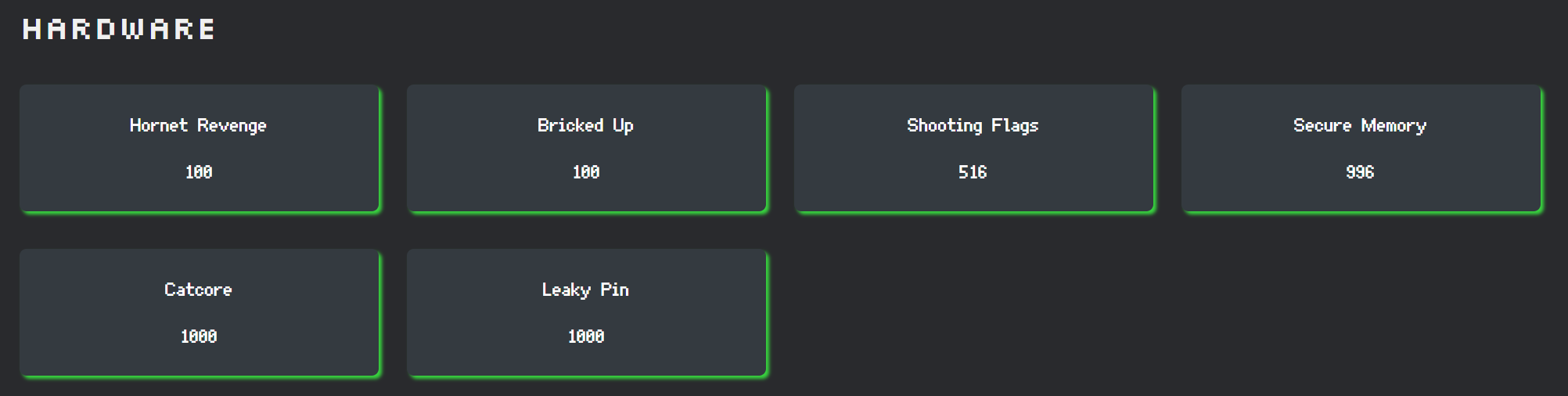
The challenges are documented at https://github.com/NUSGreyhats/greyctf25-challs/tree/master/finals/hardware, but I'll be covering challenge design, balancing and how that fits into the CTF
Hornet Revenge
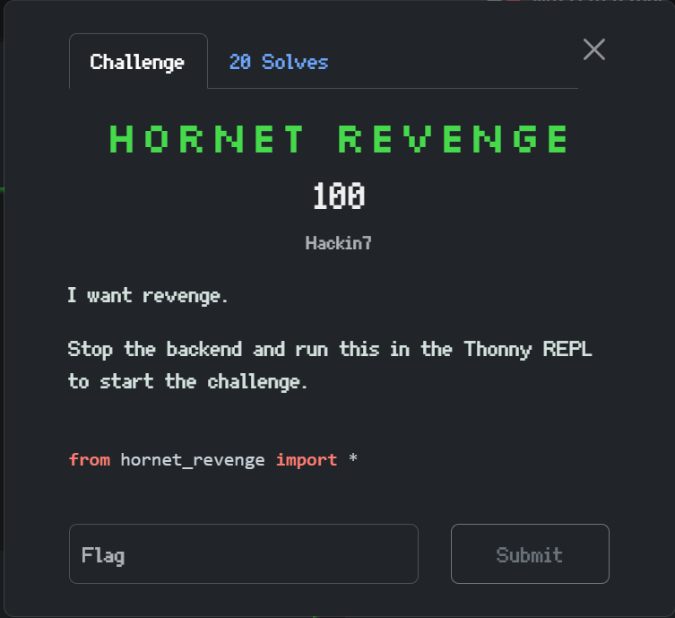
Everyone is able to solve Hornet Revenge. It was designed that way as a Googleable Q&A challenge such that people have some understanding of how to begin. This references last year challenges, we combined them into one more substantive challenge this year.
To solve some issues with last years' Q&A, I made it case insensitive, MCQ at times, and made the answer format clearer (with question marks).
In hindsight I should have taught people how to use the GPIO Pins here, but oh well.
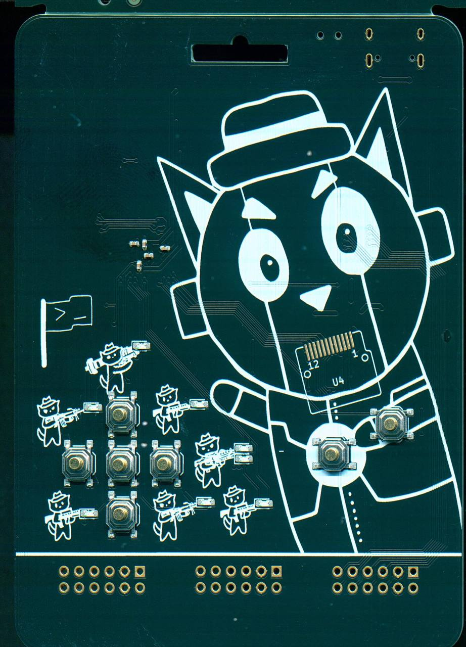
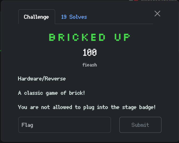
Shooting Flags
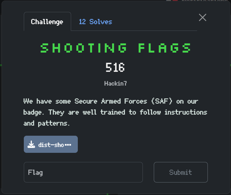
Shooting Flags is meant to be an introductory FPGA challenge. I give the participants some verilog code and they understand it, and reverse the LED patterns to get the flag.
I think the number of solves was about right, I was worried that the participants would struggle more as they didn't solve this challenge in the 1st 4 hours or so in the CTF, but after the 1st solve I'm glad people got it rather easily.
Secure Memory
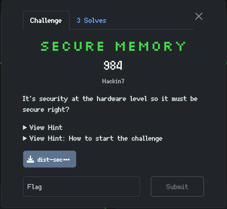
This challenge was inspired by hardware race conditions. The clock speed was slowed down to 15Hz such that it is relatively easy to exploit.
The basic idea is that the memory read is synchronous while the address whitelisting is asynchronous. So what we can do is as such
- Set the memory address to a desired address
- Wait for the memory to give the related value
- Quickly change the memory address to a white listed value
The synchronous memory output would not have updated yet but the check would allow the value through, such that we can leak out the memory values at the desired addresses. It is a CWE-1280: Access Control Check Implemented After Asset is Accessed [17]
A lot of people told me it was a TOCTOU attack. To be frank I never heard of the term before this lol. But I guess it's similar, a hardware race condition.
The interesting challenges when setting this challenge was making the code not obvious what vulnerability it was (but in the end it was rather easily ChatGPTed). But something interesting I realised is that people didn't know how to interface with CatCore and Secure Memory. The template code provided wasn't substantative enough (I think people didn't know how to use GPIO even). In the future guiding participants on what GPIO (pins which allow you to input and output signals) is could be useful but for a hotfix during the CTF, I showed more template code which got (1) more people to solve the challenge.
I would have liked if more people (eg. 7 people) solve this challenge, but I think it was still ok. I think Secure Memory is a challenge that can really get people thinking about what hardware is like. They would have to understand verilog and what its like (or ChatGPT), and how they could exploit it through wiring the secure memory to the RP2350 and exploiting it. It showcases a hardware (expressed as verilog), to deconstruct the idea of what "hardware" is. And I would say its the highlight challenge of the badge, only possible with an FPGA (its not really the same if you sim it).
I left a sped up version of Secure Memory in the badge, I'm not sure if its solvable but if anyone solved it do let me know by email or other social media! It probably needs PIO to be fast I think.
CatCore
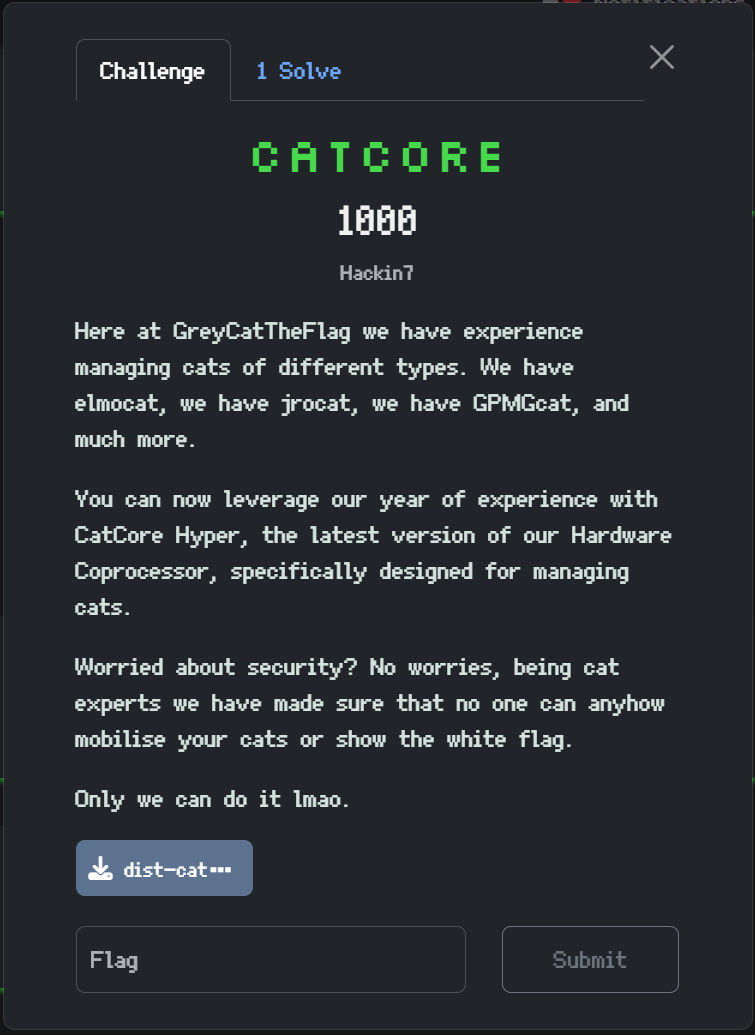
CatCore as a challenge took ridiculously long (5 weeks!!!) to ideate, mainly because I wanted to use it to truly explore realistic, low level hardware vulnerabilities. While I didn't manage to fit on all the ideas I had (I was planning something inspired by meltdown), and it wasn't as ambitious as I hoped it would be, I think I did get something interesting.
Making it reflective of real world CPU vulnerabilities and still solvable by the GreyCTF participants was a huge challenge, and I didn't want it to be too similar to of secure memory.
My main inspirations were game console vulnerabilities, I was looking at more specifically, the Wii Twiizers vulnerabilities (shorting & window attack to leak the keys), as well as the Xbox 360 reset glitch/ JTAG attack (send the message).
What is CatCore?
The titular CatCore is documented in the pdf on the badge. It has various led and comfiguration modes. More interestingly, it has different privilege levels
- Normal - for setting the leds regularly etc.
- Developer (imagine it like android or xbox developer mode/ unlocked bootloader) - you can run more privileged commands but you don't have full control
- Admin - you need to sign the command to run it. It only works for the most privileged commands, ideally only those by the system designers.
This layering system was heavily inspired by game consoles. You can do your normal tasks, but to have control of the system, you need to either
- Get developer mode (eg. Xbox One - pay for access)
- Run authorised code (eg. Games, they are signed with the private keys)
After looking through the documentation, the path people should have ideated would be something like this:
- Somehow get the admin keys
- Sign the command and get the flag
But maybe jumping straight into the admin keys is too far, so maybe getting more privileges step by step is better.
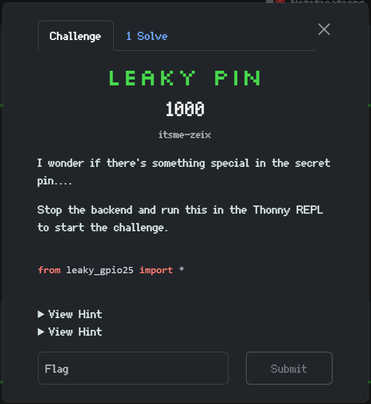
Developer mode
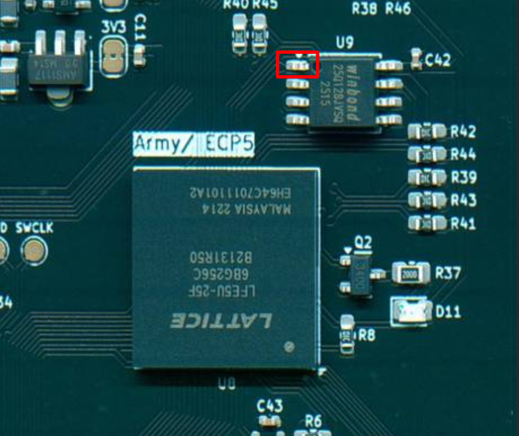
On looking at the documentation, you would notice that we can access developer mode by setting a pin to ground. However, identifying the pin is troublesome, especially it was not labelled in the PMODs.
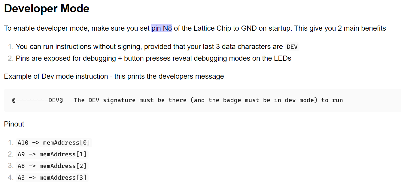
The intended path to access developer mode is to check the pin out of the LFE5U-25F chip, and notice the pin is actually supposed to be connected to CS of the flash chip. Alternatively, tracing through secret development kit would get the same result. Once done, short the pin to ground on uploading of the bit stream. The CatCore would then be in developer mode.
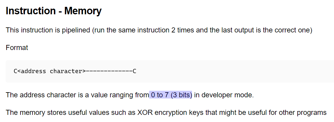
Leaking keys
The next thing to take note is that there is a mode to view the "memory" in CatCore. But you can only view the specific view keys, and if you tried all the ones you found so far, it wouldn't work.
The key is to notice the difference in documentation, you can set a 3 bit address value. but 4 bits are exposed through the PMOD. We can set the bits through the mods to set the address
In Developer Mode

After you have the keys you can just brute force them, XORing all possible keys with the Flag Reading command to get the flag. This part was inspired by the Wii Twiizers attack, just by shorting pins externally do you gain access to all the private keys of the console.
This challenge also required participants to understand how the CatCore system works, the idea is that they can read the FPGA overlay code and understand it. However, in the end, I think that was also a significant barrier to most from solving the challenge, as it needed them to understand the badge.
Other Challenges
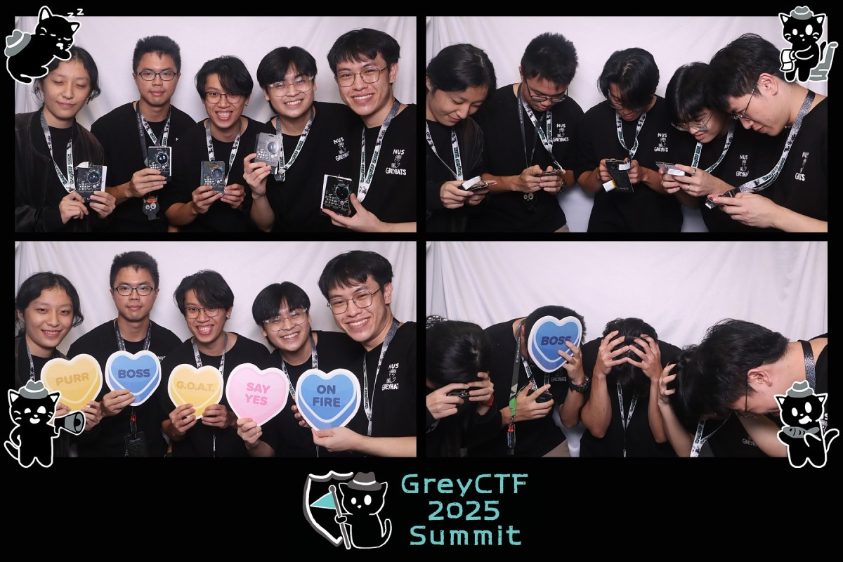
I thought it would be nice to have Tetris on the badge considering the gooners we have lmao.
If you have a tetris badge I'll buy it ~ yiqian 2k25
I got Yu Zhang to do a Tetris game from a badge, and maybe can add in a small challenge. To be frank I wasn't sure how it can fit into greyctf (elmo didn't want too many hardware challenges) but making it a stage challenge was quite fun and a nice move. Always nice to see people gooning on stage lmao.
I wanted a PIO challenge and I thought to be frank, it should be rather doable by many people.
However I guess many didn't know to start thinking of PIO, and that hindered the challenge.
Overall
Overall, I felt satisfied with the challenges, although they were hard and not as many solved as I would have liked, the few that solved were inspired. I remember scufFed talking to me how easy CatCore was in hindsight and how inspiring it can be.
I'm also just glad people didn't reverse the bitstream directly lol, I think it would be too hard (though there are documentation online). The people that tried struggled lmao.
Extra
khian vibecoded asteroids wtf
sayo got bad apple wtf
I whacked out spamgame, its a game that has been stuck with me since primary school lmao, rather braindead.
Conclusion
Hopefully all these considerations were interesting to hear! As much as the badge is meant for GreyCTF, GreyMecha/Army is also an immense passion project and a celebration of how far NUS GreyHats has come, and I hope you guys enjoyed it!
Badge Team that made it happen
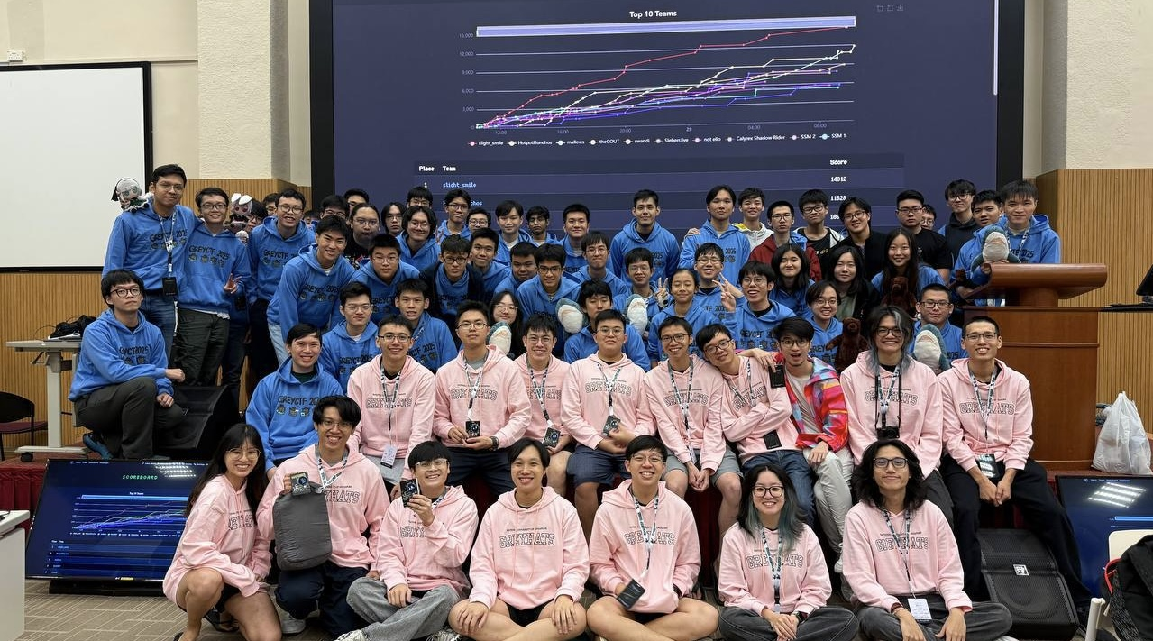
Finalists