A Summer's Pain in STM32
So I've been doing a LOT of STM32 (and HAL coding) over the summer. I've worked on these related projects
- Hornet 9.0 Acoustics (was trying to repurpose the board into something interesting)
- GreyCat2K24
- Bumblebee Actuation Backplane PWM Code
STM32 is this relatively interesting architecture to me. It's an ARM architecture, so it's quite popular. You hear it used everywhere, in CPU motherboards, industrial systems, robotics, and much more. However, as a hobbyist, I have never heard much about it before Hornet 9, most of the attention being focused on other Microcontrollers such as the Arduino, ESP32, Microbit, Raspberry Pi Pico. You never really see a Bluepill in Sim Lim Tower. I wanted to cover more on this architecture.
Hardware
Development Boards
Some of the more advanced STM32 development boards include the Nucleo and STM32 Discovery series of boards. However, in this case, we will be focusing on the STM32 Blue Pill.
You would usually use an onboard programmer (STLink) to program one of these through Serial Wire Debug (SWD). However, for the Blue Pill, it doesn't have such a programmer, and you would need to buy one. You can get an STLink or a JLink. A JLink is generally preferred because it has more functionality such as SEGGER RTT (you can send ASCII data instead of needing a separate UART peripheral).
Custom PCB
As for implementing the STM32 Chip on a PCB, these are my general guidelines for implementing it on a PCB:
- External Oscillator
- High power Oscillator - good to implement, needed for peripherals like USB
- REMEMBER TO GROUND YOUR OSCILLATOR CAPS
- Low Power Oscillator generally not needed, but depends on use case
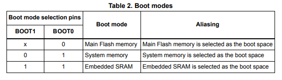
- BOOT0 (and BOOT1)
- Generally you would want a pulldown for BOOT0, but you might want to pull BOOT0 high to run the onboard bootloader. That bootloader might allow you to program through other means (eg. UART, USB, maybe even CAN? - do check your data sheet)
- Reset button?
- SWD Pins (for programming)
A general good raw of thumb is to follow the bluepill schematic, and adjust as needed
https://community.st.com/t5/stm32-mcus-products/hi-what-is-boot0-in-stm32/td-p/426914
https://stm32world.com/wiki/Boot0
Setup
So the STM32 chip is implemented on a PCB, and you want to get the chip running code and able to work. Now what?
Development Environment
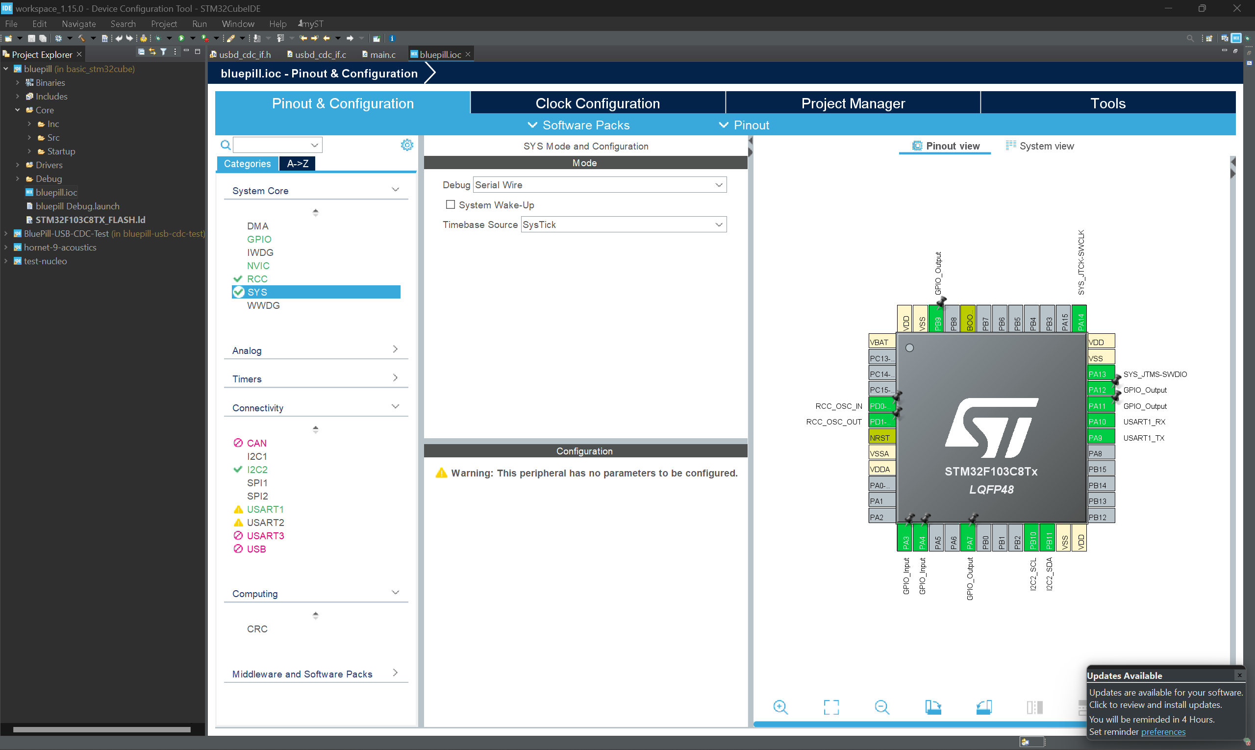
For the sake of this article, we will not be discussing STM32duino, and will be focusing more on STM32CubeIDE and STM32 HAL (Hardware Abstraction Layer) Libraries. With the HAL Libraries, you get more control over the peripherals of the MCU, such as the Timers, USB, etc. (also I couldn't really get STM32duino working well for my use cases). There are many good guides online on how to use HAL to turn on/off LEDs, PWM, use SPI and much more.
The general workflow is to configure the peripherals of the MCU through the .ioc editor (STM32CubeMX), generate HAL code, and then add your own code to get the program. The configuration and generation of code can be done through the Eclipse-based STM32CubeIDE.
Personally I used PlatformIO with the HAL libraries. The stm32pio tool allows you to generate HAL code from the .ioc file into the PlatformIO project easily.
Oscillators
So the STM32 series (usually) has an internal oscillator, and you can connect external high power and low power oscillators. If, for instance,
One way to identify if there is an issue with the oscillators is if something like this happens
no just error stuck in error handler loop when you debug
in systemclock config function
In STM32CubeMX, you can configure the oscillators. Here's an example of the UI.
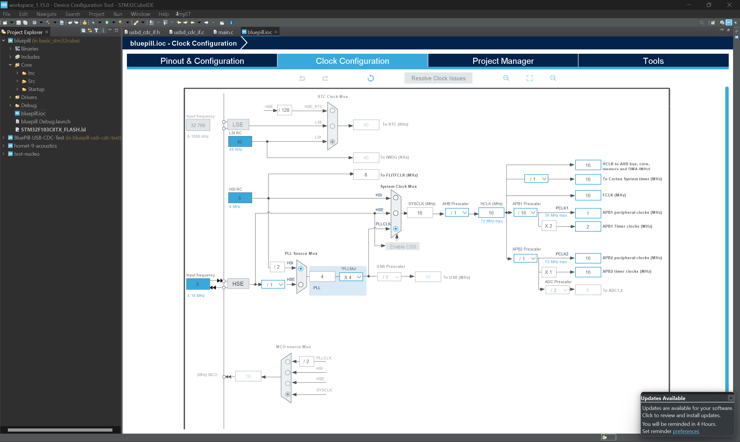
I suggest testing using only the internal oscillators first, before trying to get the external oscillators to work. At least with the internal oscillators you can still run code to blink LEDs.
If the external oscillators are not working, you can double check your schematic. Personally this link helped me identify that it was a capacitor grounding issue.
Please check reset
Another possible reason as to why a board is not working is that reset is always pulled low. This happened to 1 of the PCBs I was testing, the reset button footprint was wired wrongly.
Right now we facing programming issue
The stlink and j link cannot connect to the mcu
For the stlink when we try upload it says cannot reset mcu, but the mass storage device itself has no fail.txt
Type "connect" to establish a target connection, '?' for help
J-Link>connect
...
Connecting to target via SWD
InitTarget() start
SWD selected. Executing JTAG -> SWD switching sequence.
DAP initialized successfully.
Timeout while waiting for CPU to halt.
Can not attach to CPU. Trying connect under reset.
SWD selected. Executing JTAG -> SWD switching sequence.
DAP initialized successfully.
Timeout while waiting for CPU to halt.
Connecting to CPU via connect under reset failed.
InitTarget() end - Took 1.20s
Connect failed. Resetting via Reset pin and trying again.
InitTarget() start
SWD selected. Executing JTAG -> SWD switching sequence.
DAP initialized successfully.
Timeout while waiting for CPU to halt.
Can not attach to CPU. Trying connect under reset.
SWD selected. Executing JTAG -> SWD switching sequence.
DAP initialized successfully.
Timeout while waiting for CPU to halt.
Connecting to CPU via connect under reset failed.
InitTarget() end - Took 1.21s
Error occurred: Could not connect to the target device.
For troubleshooting steps visit: https://wiki.segger.com/J-Link_Troubleshooting
J-Link>
Debug
Initially, I was confused as to why my GreyCat PCB kept disconnecting from SWD once it started running code. I had to boot it into the bootloader using BOOT0 to get the SWD to work.
On looking at the .ioc file, I realised that Serial Wire Debug needed to be enabled for it to work in the program. In hindsight, this makes sense, as you don't want random hackers dumping your firmware through SWD in a production ready device.
Functionality
ST7735 LCD/ SPI
I wanted to connect the ST7735 LCD to my STM32 PCB. I used th
Unlike the Arduino Framework, using the STM32 HAL libraries means you have to be more careful with configuration of the SPI bus. I wasted a fair bit of time due to misconfiguration of the SPI Bus
TLDR
- Configure speed correctly (match the device speed) in STM32 Cube. Same with bitwidth (8 bits)
- Just needed to reduce prescaler such that speed is 2MBits/s
- Copy all code from STM32cube, even in the HAL files
Fast Fourier Transform (FFT)
What is FFT
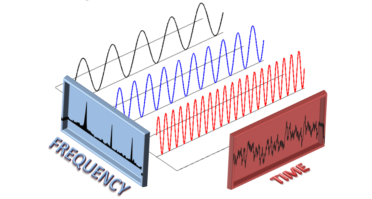
I only learnt about this when doing acoustics, but TLDR Fast Fourier Transform takes in a signal, and gives you the frequencies making up that signal.
In graph terms
- Input: Signal Value against Time graph
- eg. Audio Signal
- Output: Power against Frequency Graph
Build Configuration
You can use the CMSIS functions. To do so, you just need to configure the build flags in platformio.ini. This Github issue documents the process somewhat too.
[env:acoustics_stm32g4]
platform = ststm32
board = stm32g473cb
framework = stm32cube
build_src_filter =
	+<acoustics_stm32g4/>
	+<common/>
monitor_speed = 115200
#lib_deps = mbed-xorjoep/CMSIS_DSP_5@0.0.0+sha.4098b9d3d571
#board_build.stm32cube.custom_dsp_library = yes
build_flags =
  -larm_cortexM4l_math
The ADC Sampling rate is calculated from the frequency of the
FFT Calculate Sample Rate
My calculations were
- Max frequency = 115159
- Sample rate = 230769
I got the sampling rate calculation through (12MHz oscillator frequency)/ (PRESCALAR=4) / (10.5+2.5 clock cycles). More information can be found in your MCU data sheet, mine is at https://www.st.com/resource/en/product_training/STM32G4-Analog-ADC.pdf, Page 20.
However, I suspect I screwed up my calculations somewhere, so I (in classic hacky fashion) tweaked the sampling rate empirically to get a more accurate result.
#define SAMPLING_RATE (230769*5.5)
Readings on STM32
- 20kHz = 21071
- 5kHxz = 4970 or so
- 50kHz = 52000 or so
!Pasted image 20240522163935.png
Reference Code
Here's some reference code I wrote. The important thing is that the arm_rfft_fast functions take in the ADC values in fft_input, and return the FFT in the fft_power array. The frequency is calculated from the index of that array multiplied by the frequency resolution.
// https://klangstrom.dennisppaul.de/2021/08/30/FFT-with-CMSIS-DSP-Library.html
#include "math.h"
#include "arm_math.h"

//#define SAMPLE_BUFFER_LENGTH        4096
#define SAMPLE_BUFFER_LENGTH        1024
#define SAMPLE_BUFFER_LENGTH_HALF   (SAMPLE_BUFFER_LENGTH/2)
//#define SAMPLING_RATE               48000 // need to change for ADC's sampling rate
#define SAMPLING_RATE (230769*5.5)
float fft_input[SAMPLE_BUFFER_LENGTH];
float fft_output[SAMPLE_BUFFER_LENGTH];
float fft_power[SAMPLE_BUFFER_LENGTH_HALF];

uint8_t     ifftFlag                = 0;
float       frequency_resolution    = (float)SAMPLING_RATE / (float)SAMPLE_BUFFER_LENGTH;

uint32_t fft_max_freq = 0;
uint32_t fft_max_power = 0;

void FFT_Preprocess_Dummy(){
	// write signal to array
    for (int i = 0; i < SAMPLE_BUFFER_LENGTH; i++) {
        float r = (float)i / (float)SAMPLING_RATE;
        r *= 3.14159265359 * 2;
        r *= 880; // frequency in Hz
        float s = sin(r) + sin(r * 4) * 0.5 + sin(r * 3) * 0.25;
        fft_input[i] = s;
		//printf("%i: %i,", i, (int)(fft_input[i]*1000));
    }
}

void FFT_Analysis(){
	// analyze signal
    arm_rfft_fast_instance_f32 fft;
    arm_rfft_fast_init_f32(&fft, SAMPLE_BUFFER_LENGTH);
    arm_rfft_fast_f32(&fft, fft_input, fft_output, ifftFlag);
    arm_cmplx_mag_f32(fft_output, fft_power, SAMPLE_BUFFER_LENGTH_HALF);
    for (int i = 1; i < SAMPLE_BUFFER_LENGTH_HALF; i++) {
        //printf("%i\tfrq: %.1f\tenergy %.6f\r\n", i, i * frequency_resolution, fft_power[i]);
        //printf("%i\tfrq: %.1f\tenergy %.6f\r\n", i, 0, fft_power[i]);
		//printf("%i:\t", i); printf("frq: %i\t", (int)(i * frequency_resolution)); printf("nrg: %i\t,", (int)fft_power[i]); // Working
    }

	// Finding Frequency with the max power
    float32_t   maxValue=0;
    uint32_t    maxIndex=0;
    //arm_max_f32(fft_power, SAMPLE_BUFFER_LENGTH_HALF, &maxValue, &maxIndex);

	// Manually Calculate max because its not working
	for (int i = 1; i < SAMPLE_BUFFER_LENGTH_HALF; i++) {
		if (fft_power[i] > maxValue){
			maxValue = fft_power[i];
			maxIndex = i;
		}
    }

    //printf("\r\n");
	printf("max power: %i\t", (int)maxValue);
    printf("max index: %i\t", maxIndex);
    printf("frequency: %i\t", (int)(maxIndex * frequency_resolution));
	fft_max_freq =(maxIndex * frequency_resolution);
	fft_max_power = (int)maxValue;
}


//#define ADC_SCALE 4096 // 12 bit max value
#define ADC_SCALE 1024 // 12 bit max value
#define ADC_FFT_INDEX 0
//#define ADC_FFT_BUF_LEN (ADC_BUF_LEN/2)
#define ADC_FFT_BUF_LEN 1024
#define ADC_FFT_BUF_LEN_HALF (ADC_FFT_BUF_LEN/2)
//float adc_fft_input[SAMPLE_BUFFER_LENGTH];
void FFT_Preprocess_ADC(){
	// Preprocess ADC Data
	// Normalisation
	for (int i=0; i<ADC_FFT_BUF_LEN; i++){
		fft_input[i] = (float32_t)((float)current_adc_data[ADC_FFT_INDEX][i]/ADC_SCALE);
		//printf("%i: %i,", i, (int)(fft_input[i]*1000));
	}
	//arm_scale_f32(current_adc_data[ADC_FFT_INDEX][0], (float)1/ADC_SCALE, fft_input,ADC_FFT_BUF_LEN); // Dosnt work because need convert value
}
In the main function and other HAL functions
int main(){
HAL_Init(); // Reset of all peripherals, Initializes the Flash interface and the Systick.
SystemClock_Config(); // Configure the system clock
/* Initialize all configured peripherals */
MX_GPIO_Init();
MX_DMA_Init();
MX_USART1_UART_Init();
MX_ADC1_Init();
MX_ADC2_Init();
MX_ADC3_Init();
MX_ADC4_Init();
...
HAL_ADC_Start_DMA(&hadc1, (uint32_t*) adc_buf[0], ADC_BUF_LEN);
HAL_ADC_Start_DMA(&hadc2, (uint32_t*) adc_buf[1], ADC_BUF_LEN);
HAL_ADC_Start_DMA(&hadc3, (uint32_t*) adc_buf[2], ADC_BUF_LEN);
HAL_ADC_Start_DMA(&hadc4, (uint32_t*) adc_buf[3], ADC_BUF_LEN);
...
FFT_Preprocess_ADC();
FFT_Analysis();
printf(
"ADC Values: [%d], [%d], [%d], [%d] \n", current_adc_data[0][0], current_adc_data[1][0],
current_adc_data[2][0], current_adc_data[3][0]
);
...
}
..
void ADC_Callback_Func(ADC_HandleTypeDef* hadc, bool full)
{
int current_adc;
if (hadc->Instance == ADC1)
current_adc = 0;
else if (hadc->Instance == ADC2)
current_adc = 1;
else if (hadc->Instance == ADC3)
current_adc = 2;
else if (hadc->Instance == ADC4)
current_adc = 3;
newADCData[current_adc] = true;
memcpy(
¤t_adc_data[current_adc][0], &adc_buf[current_adc][full * (ADC_BUF_LEN / 2)],
ADC_BUF_LEN * sizeof(uint16_t) / 2
);
}
I think this Youtube video by Phil's Lab is also a good example of how to implement FFT on the STM32.
STM32 Bluepill USB CDC
For the Bluepill to use USB, the External High Speed Oscillator needs to be connected to the chip. For most bluepills, this is already done, but when implementing the bluepill schematic on a custom PCB, the oscillator is an additional point of failure.
I was stuck on how to configure USB through the ioc file manually and get it to show a virtual COM port. Thankfully, there is a sample project online at https://github.com/philrawlings/bluepill-usb-cdc-test. I started a project off this sample code.
I ended up writing some functions to enable prinf and so on for ease of use of the USB CDC functionality. (not the most ideal way to write it, but a simple enough implementation that gets the job done)
// Another fast function is putchar
void fastPrintString(char *string_given){
  while (CDC_Transmit_FS((uint8_t *)string_given, strlen(string_given)) == USBD_BUSY){};
}

void usbPrintf(int len, char *fmt, ...)
{
   va_list arg_ptr;
   char buf[len+1];

   va_start(arg_ptr, fmt);
   int written_len = vsnprintf(buf, len, fmt, arg_ptr);
   buf[written_len] = '\0';
   fastPrintString(buf);
   va_end(arg_ptr);
}

int readString(char *outputBuf, int len){
  // Read buffer
  uint8_t rxData[1];
  memset(rxData, 0, 1);
  uint8_t buf_pos = 0;

  while (1) {
    // Echo data
    rxData[0] = __platform_getchar();
    if (rxData[0] == '\n' || buf_pos >= len){ break; }
    outputBuf[buf_pos] = rxData[0];
    buf_pos++;
  }
  return buf_pos;
}

uint64_t readInteger(){
  char buf[MAX_BUF_LEN];
  readString(buf, MAX_BUF_LEN);
  // return atoi(buf);

  char *endptr;
  uint64_t num;

  // Convert the string to a long integer
  num = strtoull(buf, &endptr, 10);
  if (endptr == buf) {
    usbPrintf(MAX_BUF_LEN, "No digits were found.\n");
    return 0;
  } else if (*endptr != '\0') {
    //usbPrintf(MAX_BUF_LEN, "Invalid character: %c\n", *endptr);
  } else {
    //usbPrintf(MAX_BUF_LEN, "The number is: %ld\n", num);
  }
  return num;
}
STM32 Bluepill DFU Bootloader
I was researching ways to upload code through USB on a bluepill. This led me to dapboot.
Usage
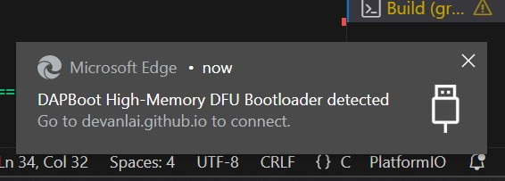
When the STM32 runs dapboot, a prompt automatically shows up on my computer to open this webpage.
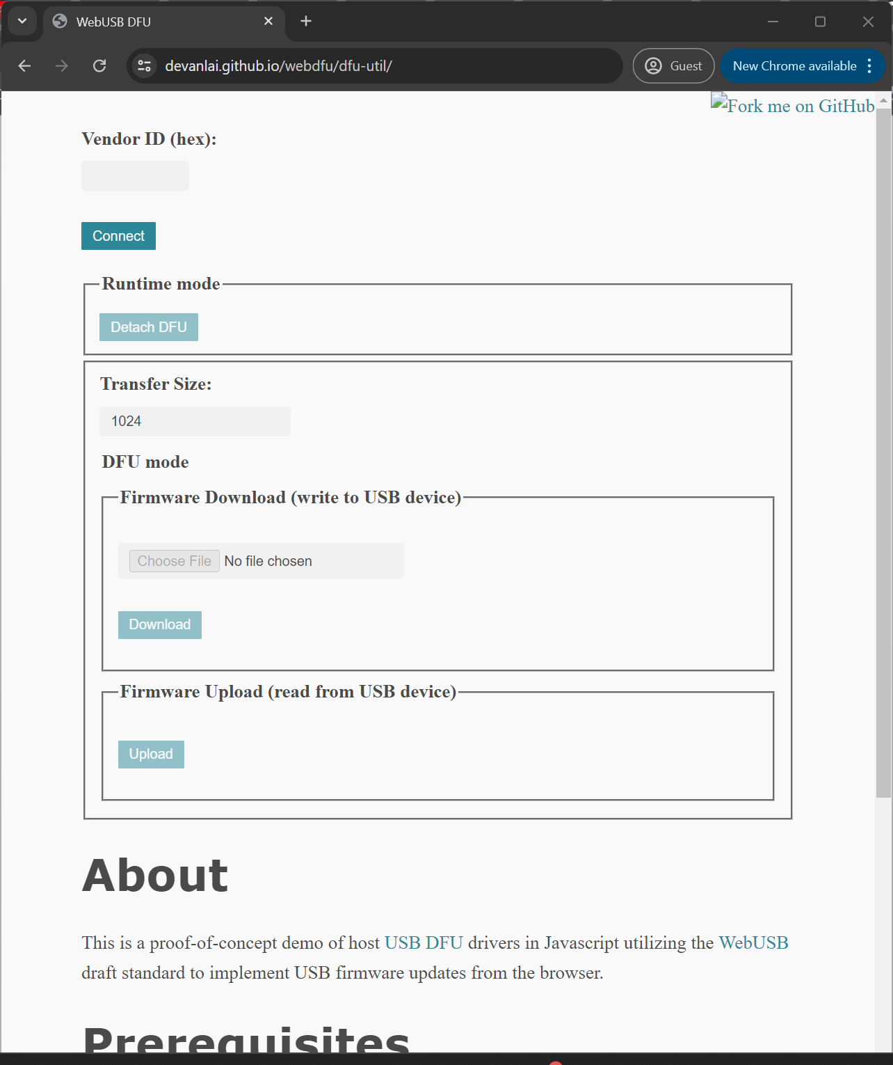
I personally haven't tested whether the dfu mode works with other utilities, but the STM32 board is considered a DFU device, so theoreitcally, it is possible.
Another point to take note is to REFRESH the page when you change the binary. Else (especially if the old and new binary have the same path), the webpage might not actually upload a different binary compared to before.
Configuration & Recompilation
For the GreyCat2K24 Badge, I decided to make that into a Glitching CTF Challenge to test CTF players on the BOOT1 pin in affecting the boot process (and thus, the boot process). Dapboot had to be recompiled, setting the pin as active high, and enabling an internal pull (since that was not put on the PCB).
The related files can be found in dapboot-master\src\stm32f103\bluepill\config.h
#ifndef HAVE_BUTTON
#define HAVE_BUTTON 1
#endif
#ifndef BUTTON_ACTIVE_HIGH
#define BUTTON_ACTIVE_HIGH 1 // For BOOT1 - make sure its high
//#define BUTTON_ACTIVE_HIGH 0 // For BTN1
#endif
#ifndef BUTTON_GPIO_PORT
#define BUTTON_GPIO_PORT GPIOB
#endif
#ifndef BUTTON_GPIO_PIN
#define BUTTON_GPIO_PIN GPIO2 // For BOOT1
//#define BUTTON_GPIO_PIN GPIO12 // For BTN1
#endif
// Blue-Pull has 100k resistors on PB2, so we can't use weak pulls to read it.
#ifndef BUTTON_USES_PULL
//#define BUTTON_USES_PULL 0 // Default
#define BUTTON_USES_PULL 1 // set a pull
#endif
Compilation instructions are in the dapboot GIthub Repo, I compiled it for the 64kb bluepill with high memory. (I tried uploading a 128kb high memory binary on the GreyCat board before, and it didn't go through, likely because they locked off that section of memory)
Reboot into Bootloader from Code
To do so, you would need to configure the RTC, and modify the RTC Registers. Here's an example
#define CMD_BOOT 0x4F42UL

#define BOOT_FLAG_LEN 30
// grey{what_flag_just_boot1_bro}
uint8_t boot_flag_array1[BOOT_FLAG_LEN] = {20, 99, 10, 94, 20, 9, 46, 98, 9, 7, 57, 56, 30, 100, 86, 88, 48, 41, 56, 72, 31, 78, 26, 9, 4, 86, 14, 54, 100, 34};
uint8_t boot_flag_array2[BOOT_FLAG_LEN] = {115, 17, 111, 39, 111, 126, 70, 3, 125, 88, 95, 84, 127, 3, 9, 50, 69, 90, 76, 23, 125, 33, 117, 125, 53, 9, 108, 68, 11, 95};
void chall_bootloader(){
    usbPrintf(MAX_BUF_LEN, "\nEnter flag to reboot into bootloader> ");

    uint8_t input_ans[BOOT_FLAG_LEN+1];
    memset(input_ans, 0, BOOT_FLAG_LEN+1);
    uint8_t ans_len = readString(input_ans, BOOT_FLAG_LEN);
    usbPrintf(MAX_BUF_LEN, "%s\n", input_ans);

    if (ans_len != BOOT_FLAG_LEN){
        usbPrintf(MAX_BUF_LEN, "WRONG!!!");
        return;
    }

    for (int i=0; i<BOOT_FLAG_LEN; i++){
        if ((input_ans[i] ^ boot_flag_array1[i]) != boot_flag_array2[i]){
            usbPrintf(MAX_BUF_LEN, "WRONG!!!");
            return;
        }
    }

    // Reboot into bootloader
    badge_state_set_unlock_status_bit(UNLOCK_BIT_PURPLEHAT);

    HAL_RTCEx_BKUPWrite(&hrtc, RTC_BKP_DR1, CMD_BOOT);
    usbPrintf(MAX_BUF_LEN, "Success - Press reset to reboot into bootloader!!!");
    //usbPrintf(MAX_BUF_LEN, " - bootloader not implemented yet\n");
    ans_len = readString(input_ans, BOOT_FLAG_LEN);
}
Most
STM32 Bluepill Flash Memory
Handling Flash is a whole other issue to deal with. The initial plan was for GreyCat to store its states to an EEPROM, such that even when you power cycle the board, it would still be able to remember the states.
However... there is no EEPROM.
An alternative solution would be to use the onboard Flash Memory. To make it easier to handle the flash memory, I used a union of a struct and an integer array. The array representation of the data helps a lot in writing the data to the flash memory
#define STATE_NAME_SIZE 24
#define STATE_STRUCT_SIZE 4
typedef struct BadgeState{ // 256 bits = 64 bit * 2
  uint8_t name[STATE_NAME_SIZE];              // 22 * 8 = 192 bits
  uint64_t unlock_status; // 64 bits
} badge_state;

#define STORAGE_ADDR (0x0801FC00-1024*(64+8))// last page of STM32F103C8T6
#define STORAGE_ADDR_IMAGE (0x0801FC00-1024*(64+8+1)) // last page + leave space for bootloader (8 + 1)

typedef union FlashPage1{
  uint64_t memory[STATE_STRUCT_SIZE];   // [128]; // 64 bits = 8 bytes
  badge_state state;
} flash_page_1;
uint32_t flash_page_erase(uint64_t page_address, uint64_t no_pages){

   //Instantiate the FLASH_EraseInitTypeDef struct needed for the HAL_FLASHEx_Erase() function
  FLASH_EraseInitTypeDef FLASH_EraseInitStruct = {0};

  FLASH_EraseInitStruct.TypeErase = FLASH_TYPEERASE_PAGES;    //Erase type set to erase pages( Available other type is mass erase)
  FLASH_EraseInitStruct.PageAddress = page_address;            //Starting address of flash page (0x0800 0000 - 0x0801 FC00)
  FLASH_EraseInitStruct.NbPages = no_pages;                    //The number of pages to be erased
  uint32_t  errorStatus = 0;
  if (HAL_FLASHEx_Erase(&FLASH_EraseInitStruct,&errorStatus) != HAL_OK)
  {
    /*Error occurred while page erase.*/
    return HAL_FLASH_GetError();
  }
  return 0;
}

// Flash Operations ///////////////////////////////////////////////////////////////////////////////////
badge_state flash_read_state(){
  badge_state *badge_state_addr = (badge_state *) STORAGE_ADDR;
  return *badge_state_addr;
}
void flash_write_state(badge_state st){
  flash_page_1 page;
  page.state = st;

  HAL_FLASH_Unlock();
  flash_page_erase(STORAGE_ADDR, 1);

  for (int offset = 0; offset < STATE_STRUCT_SIZE; offset++) {
    HAL_FLASH_Program(
      FLASH_TYPEPROGRAM_DOUBLEWORD,
      STORAGE_ADDR + (offset*8), // 8 for double word
      page.memory[offset]
    );
  }

  HAL_FLASH_Lock();
}
The STM32F103C8T6 chip is known to have 128kB of Flash storage, but the 2nd 64kB is also known to sometimes be faulty. I did not want to take that risk for the final batch of boards, and modified the related addresses accordingly.
The arithmetic for how the variables are laid out in flash memory can be confusing sometimes, and it took me a while to properly understand. I referenced this article for guidance.
Timers
PWM
There are many STM32HAL PWM guides already available online, so I won't be covering them in depth. One of the more interesting things I found out is that you can reconfigure the prescalar and other related settings on the fly. I'm not too sure if this is the appropriate method, but I mainly just copied the HAL generated code over, I did not need to deinitialise the timers
void menu_usb_timer(){
    /* USER CODE BEGIN TIM1_Init 0 */

  usbPrintf(MAX_BUF_LEN, "Timer 1 Configurator\n");

  usbPrintf(MAX_BUF_LEN, "Prescalar: ");
  uint64_t prescalar = readInteger();
  usbPrintf(MAX_BUF_LEN, "%ld\n", prescalar);

  usbPrintf(MAX_BUF_LEN, "Period: ");
  uint64_t period = readInteger();
  usbPrintf(MAX_BUF_LEN, "%ld\n", period);

  usbPrintf(MAX_BUF_LEN, "CCR1: ");
  uint64_t ccr1 = readInteger();
  usbPrintf(MAX_BUF_LEN, "%ld\n", ccr1);

  /* USER CODE END TIM1_Init 0 */

  TIM_MasterConfigTypeDef sMasterConfig = {0};
  TIM_OC_InitTypeDef sConfigOC = {0};
  TIM_BreakDeadTimeConfigTypeDef sBreakDeadTimeConfig = {0};

  /* USER CODE BEGIN TIM1_Init 1 */

  /* USER CODE END TIM1_Init 1 */
  htim1.Instance = TIM1;
  htim1.Init.Prescaler = prescalar; //0;
  htim1.Init.CounterMode = TIM_COUNTERMODE_UP;
  htim1.Init.Period = period; //65535;
  htim1.Init.ClockDivision = TIM_CLOCKDIVISION_DIV1;
  htim1.Init.RepetitionCounter = 0;
  htim1.Init.AutoReloadPreload = TIM_AUTORELOAD_PRELOAD_DISABLE;
  if (HAL_TIM_PWM_Init(&htim1) != HAL_OK)
  {
    Error_Handler();
  }
  sMasterConfig.MasterOutputTrigger = TIM_TRGO_RESET;
  sMasterConfig.MasterSlaveMode = TIM_MASTERSLAVEMODE_DISABLE;
  if (HAL_TIMEx_MasterConfigSynchronization(&htim1, &sMasterConfig) != HAL_OK)
  {
    Error_Handler();
  }
  sConfigOC.OCMode = TIM_OCMODE_PWM1;
  sConfigOC.Pulse = 0;
  sConfigOC.OCPolarity = TIM_OCPOLARITY_HIGH;
  sConfigOC.OCNPolarity = TIM_OCNPOLARITY_HIGH;
  sConfigOC.OCFastMode = TIM_OCFAST_DISABLE;
  sConfigOC.OCIdleState = TIM_OCIDLESTATE_RESET;
  sConfigOC.OCNIdleState = TIM_OCNIDLESTATE_RESET;
  if (HAL_TIM_PWM_ConfigChannel(&htim1, &sConfigOC, TIM_CHANNEL_1) != HAL_OK)
  {
    Error_Handler();
  }
  sBreakDeadTimeConfig.OffStateRunMode = TIM_OSSR_DISABLE;
  sBreakDeadTimeConfig.OffStateIDLEMode = TIM_OSSI_DISABLE;
  sBreakDeadTimeConfig.LockLevel = TIM_LOCKLEVEL_OFF;
  sBreakDeadTimeConfig.DeadTime = 0;
  sBreakDeadTimeConfig.BreakState = TIM_BREAK_DISABLE;
  sBreakDeadTimeConfig.BreakPolarity = TIM_BREAKPOLARITY_HIGH;
  sBreakDeadTimeConfig.AutomaticOutput = TIM_AUTOMATICOUTPUT_DISABLE;
  if (HAL_TIMEx_ConfigBreakDeadTime(&htim1, &sBreakDeadTimeConfig) != HAL_OK)
  {
    Error_Handler();
  }
  /* USER CODE BEGIN TIM1_Init 2 */

  /* USER CODE END TIM1_Init 2 */
  HAL_TIM_MspPostInit(&htim1);


  TIM1->CCR1 = ccr1;
  HAL_TIM_PWM_Start(&htim1, TIM_CHANNEL_1);
}
Encoder Mode
On one of the projects, I was working on getting PWM working on some of the Pins. However, that didn't work too well on some of the Timers (and their related PWM Pins). On further inspection, a senior figured that it's because they were in Encoder Mode. Encoder mode is used to configure the timers to track the pulses (and hence steps) from the stepper motor's encoders. It would allow for more accurate position tracking. Here's a rough explanation by someone else on why timers configured in Encoder mode cannot be used for PWM.
re: using pwm and encoder with the same timer
- in encoder mode, the timer increments/decrements based on the outputs generated by the encoder
- in pwm mode, the timer increments periodically and compares it's counter value to the CCR register for pulse generation.
the timer behaves differently in the two modes, so it doesn't work.
very sad.
will change all encoder inputs on the mcu to extis and use interrupt-based counters for position tracking.
TLDR: Learn what your timers are configured for before anyhow trying to do PWM.
Overall
The STM32 series is a fascinating line of microcontrollers, relatively well documented, a good introduction into the lower level layers and peripherals of a microcontroller, without the pain from reading all the datasheets and understanding all the registers (hmm CG2111A). Most importantly, it is cheap yet powerful yet relatively easier to use. I highly suggest anyone free to give it a try! It might be in your next project.