GreyCat2K24 Execution Deep Dive
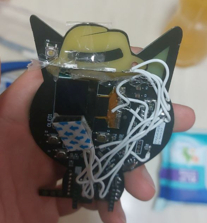
So over summer, I designed the GreyCat2K24 Badge, and I've learnt a fair bit about the different considerations designing most PCBs vs designing this PCB for mass production. GreyCat2K24 was designed using Altium Designer, and we ordered PCBA (Printed Circuit Board Assembly) through JLCPCB.
I wanted to do a deep dive in how this project was executed. Personally, this is my first ever PCB badge, and 2nd ever PCB with an onboard STM32 Chip (in fact, I only started STM32 December last year), and I'm excited to make PCB badges in the future if given the time!
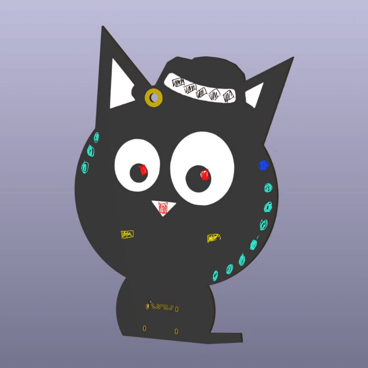
The overall concept of the badge was an STM32 Blue Pill in the shape of GreyCat, with features that light up. This was to be done in 3 months over summer before GreyCTF. However, a lot of the details had to be firmed up/ learnt along the way, and I wanted to get all the tiny details across.
1. PCB Design
1.1 Board Outline
The initial concept that I suggested was to make GreyCat into a PCB. So this was one of the concepts I whacked out in KiCAD in about an hour before we decided to actually go ahead with the project
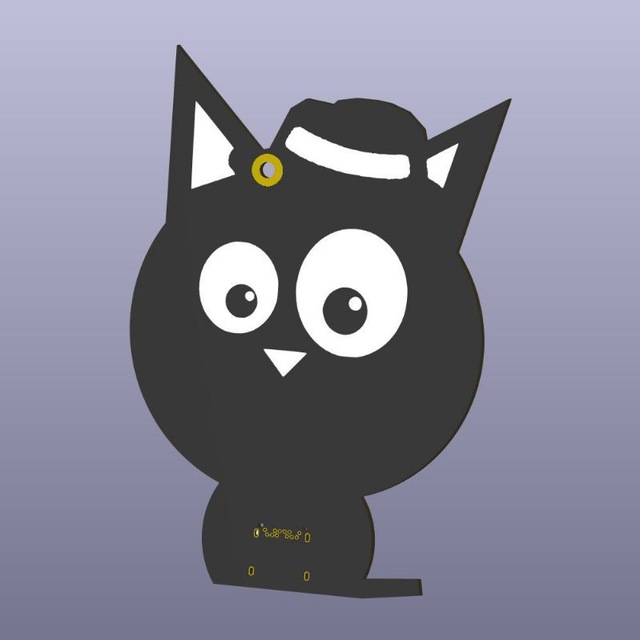
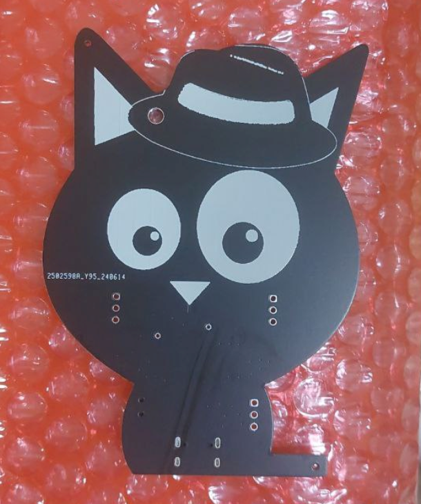
Eventually, I decided to use Altium Designer. GreyCat was in the form of an .ai (Adobe Illustrator) file, so I imported that into Inkscape, drew and modified the board outline, and imported it into Altium. Importing an SVG into altium does not result in smooth curves, but on our initial order, we figured that was a non-issue
There are some considerations
- Round the corners of the ears - hopefully to prevent it from being a hazard
- The corners of the SINCON Reloaded badge was known to be sharp
- Increase the thickness of the tail - this would hopefully prevent it from snapping off so easily (tho that could be another CTF Challenge???)
1.2 Routing
Vias and Routing
Make sure the vias are tented. Tented vias generally look OK, but untented vias might affect the look of the PCB.
Extra traces and vias on the printed side are indeed noticeable, so do plan around that. For instance, in our 2nd prototype, I rushed out the keepout zones of the ground planes, and that turned out to be quite noticeable.
Placement of Components
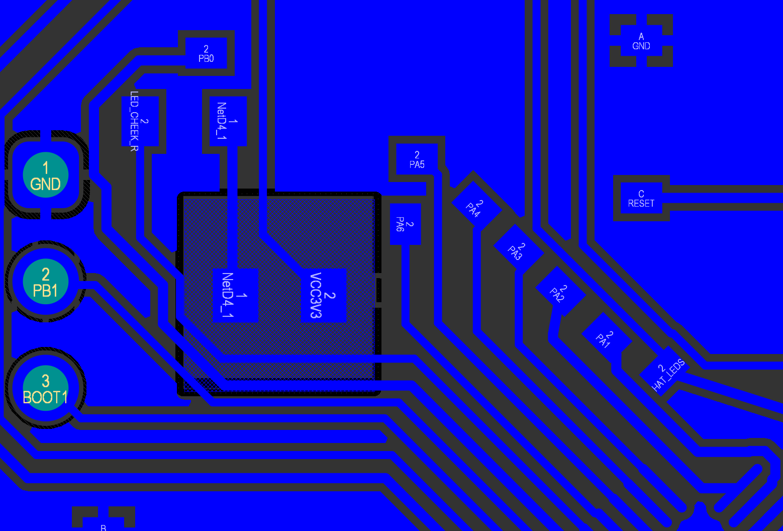
Turning chips 45 degrees helped a fair bit for routing. It made more pins accessible to 1 edge of the board (and allowed me to breakout the pins), especially important since you can't do much on the second layer on a PCB badge without vias. Shoutout to this video for inspiration! (who knew playing osu makes you a better engineer)
In hindsight, some of the assembly woes could be solved with smarter component placement. For instance, if I rotated the OLED 180 degrees, I could PCBA the OLED header instead of manually assembling them
A very useful tip for pin placement is to make your Schematic symbol match the pin layout of the chip in the actual PCB. This helped me A LOT in routing, as I could route the pins in the easiest way possible.
Another consideration was that we wanted breakout pins to the remaining IO of the microcontroller (for challenges/ experimentation). As we could not put headers (the holes would distract from the design on the PCB), I've decided to keep it as SMT pads instead. If wanted, the participants could still bend the header pins to solder them on.
We had bigger pads when we had space to route (at the body of the cat), and smaller pads for those we did not have space. It is generally good practice to breakout as much pins as possible of the chip for ease of access, you never know if you might want to make last minute tweaks to the PCB.
Routing the device itself wasn't hard, if i were to give an estimate, about 3 full days (no work, just PCB design) was needed to reach the final design. It's just that iteration and testing and meeting the DRC (Design Rule Checker) Rules takes a fair bit of time.
1.3 Lighting - PCB Material
There are a few ways to handle lighting for a PCB Badge
- Regular exposed surface mount/ THT LEDs. Basically just putting LEDs on a PCB normally
- Get the Lights to diffuse through the PCB Material
For the purposes of this article, we will focus more on the second part.
The general concept of a PCB Badge is to remove the solder mask + copper planes
- In Altium this can be done by masking out the region in the Top/ Bottom Solder Layers (depending on the effect you want to achieve)
- In Altium, Top/ Bottom Solder layers are negative layers, so putting objects there would REMOVE the soldermask on the Top/Bottom respectively - If you put silkscreen make sure to leave solder mask, else JLCPCB might remove both
- Make sure that your copper planes DO NOT BLOCK the LED lightup area, Else, when you expose the copper mask, you would just be left with copper only. You can use Altium's keepout regions to do this. (Manzel helped me identify this issue)
There are various combinations you can experiment with. (Warning, the photos might not be an accurate comparison but you can get a rough idea)
| Top Solder Mask | Bottom Solder Mask (LED mounted) | Details | Example Images |
|---|---|---|---|
| None | None | Fully expose the PCB material for better diffusion | 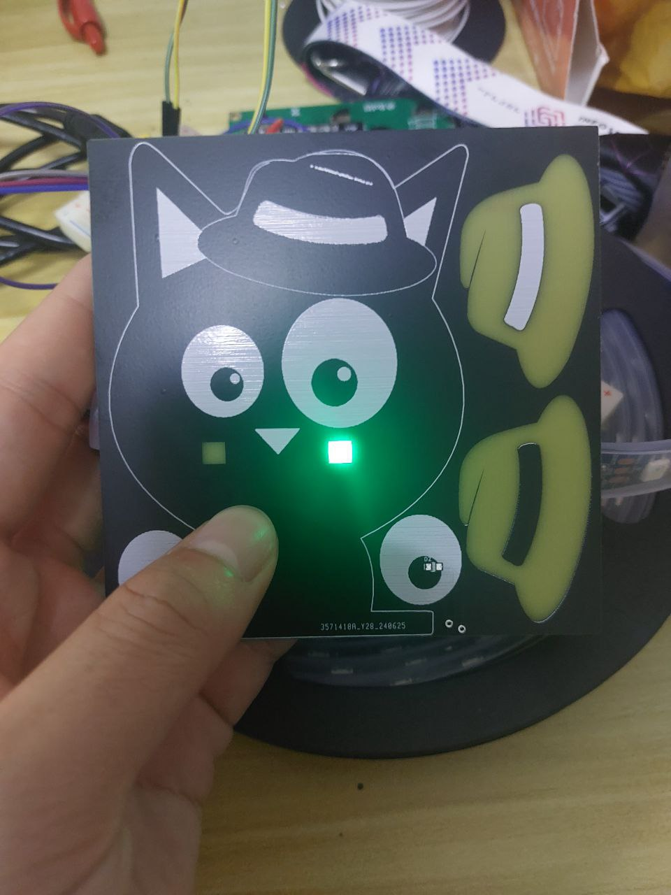 |
| Keep | None | Weaker Diffusion of Light - but you keep the colour of the PCB | 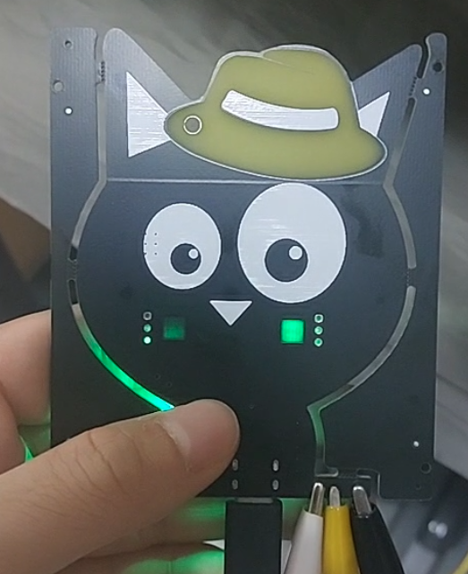 |
| Furthermore, not all colours diffuse well through the PCB. Most notably, blue doesn't really work very well through the PCB material. |
1.4 Lighting - Mounting of LEDs
Some consideration you should take note of PCB Badge considerations are
- Light Propagation
- Colour/ Texture. Do we want silkscreen?
There are generally a few ways to place LEDs
| Type | Details | Example - Front | Example - Back |
|---|---|---|---|
| Reverse Mounted | Either 1. Buy Reverse mounted LEDs for PCBA (rare & expensive) 2. Solder manually (labour intensive) |
SINCON Reloaded Badge  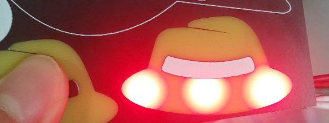 |
 |
| Front Mounted | Surprisingly, some LEDs shine even through their bottom, making it both easy to do PCBA and achieving a decent lighting effect | 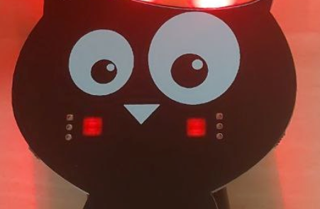 |
|
| Side Mounted | Light propagates much further but more unevenly. There are a few considerations 1. The height of the LED matters 2. Use Hot Glue to more evenly spread out the LEDs - More labour Intensive |
 |
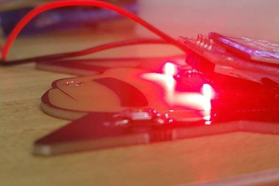 |
| Externally Mounted | In one of our GreyCat Prototypes, I used Neopixel LED strips to simulate side mounted LEDs. However, theoretically, we could adjust the position of the LED however we want to achieve the best lighting (eg. slanted at an angle) However, this is labour intensive/ not very secure, so I wouldn't recommend it |
 |
 |
1.5 Lighting - Placement & Design
We were iterating through various designs on how best to place the LEDs. Here are some sample sketches
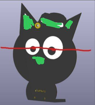
I highly recommend ordering a few test PCBs and experimenting with the various lighting positions/ configurations, it informed me on the best ways to light up the LEDs. We eventually settled on
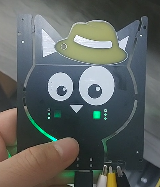
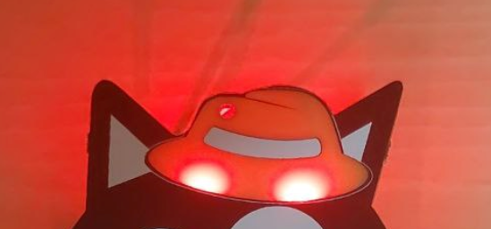
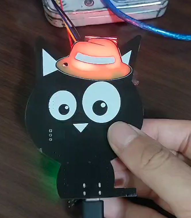
- A fully lit up hat
- We used side mounted LEDs for the hat as we wanted to cover a larger surface area, which was harder to do with reverse/ front mounted LEDs without a lot of LEDs (+it is harder to assemble).
- Blush (in the event the hat fails, we still have some interactivity)
- For GreyCat2K24, the initial design was reverse mounted LEDs for a "blush effect". However, PCBA showed us that front mounted LEDs worked well enough to achieve the desired effect.
I still think red eyes would have been funny,
1.6 Lighting - Others
I used LEDs with a 470ohm resistor in series, connected to 3.3V. This worked well most of the time, don't need too low/high resistance (normal ones work).
Some useful links on lighting PCB badges can be found here
- https://hackaday.com/tag/electronic-badge/
- https://hackaday.io/page/6081-using-side-view-leds-in-place-of-reverse-mount-leds
- https://www.instructables.com/Wings-of-Freedom-PCB-Badge/
2. Electronics
2.1 STM32
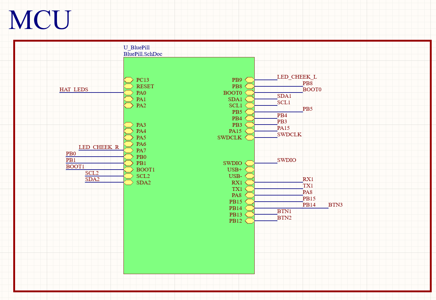
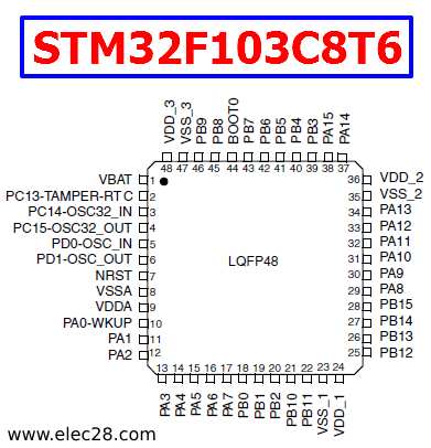
In my experience tinkering with electronics and going to Sim Lim Tower, a lot of the popular microcontrollers are the ATMega Series, and the ESP32. A few badges used the ESP32, it is a very powerful microcontroller that allows for very interesting functionalities. However, I decided on the STM32 series in the end, more specifically the STM32F103C8T6.
The STM32 microcontroller series is interesting to me because I have not seen it in a hardware badge before (at least, not in SG), and you usually won't find it in local electronics shops (Sim Lim), I have never heard about the STM32 Bluepill before joining the Hornet 9 Training Program. The STM32 Series also focused on the STM32 HAL layer, where you had more direct access to the peripherals of the microcontrollers (eg. Timers), and I thought that was interesting and something I wanted to get across.
There were some other more practical considerations, such as
- My friend implemented the STM32 Bluepill on Altium before for Hornet 9, and I was thinking it could be a good reference
- I had to make some tweaks and changes to the schematic to make it work well for the context though.
- The STM32 Bluepill is readily available, we can buy a few and start prototyping firmware while the PCBAs were being delivered.
- I was also in Bumblebee CCA, and learning how to use STM32 (and by extension Altium) would help me significantly in the CCA
- This is why I didn't use KiCAD. Even though KiCAD is free and open source, and the design files are more easily accessed by everyone (no need pay for software). I wanted to get good at Altium, which I did, I've learnt a lot of Altium's features.
- Altium Designer is free to use for students.
Eventually, a big benefit (I didn't even think about) of using STM32 is that it is much, MUCH cheaper than an ESP32. An STM32F103C8T6 is about 1 dollar, while an ESP32-S3 module is about 6.5 dollars.
2.2 OLED
OLED was to be very honest a rough decision to make, because it is NOT needed for the CTF Challenges (though the "Name" challenge used the OLED to set up the context of the problem) Personally, I feel an OLED would make the Badge so much more meaningful, because it allows you to do funny menus and have interesting features not available elsewhere. However, I was concerned about the budget, if it was worth it to pay more for a more fun badge.
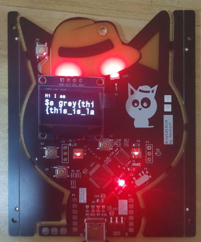
In the final firmware, the OLED was used as a way to display the participant's names, so that worked out well. The front of the badge displayed the cat, while the back of the cat displayed your name, acting as a dual purpose badge, something I really liked.
A few participants managed to do some interesting with the badges, so I feel it was absolutely worth it.
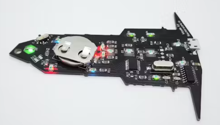
2.3 Battery Holder
My initial idea was to not put a battery holder, I rather fit in more features into a badge (OLED) rather than put a battery. I believe that when most people keep the badge, they won't have the patience to find batteries to put into the badge, but with extra features, it would be more fun to play with the badge in the long run (not that long run tho). However, there were some conflicting opinions, especially since the batteries were needed to make the hat light up.
I eventually managed to find a way to squeeze in a 2 x AAA battery holder by gluing it to the PCB and stacking it on top of some components. And putting in a battery was absolutely worth it, as I could wear the badge around with the lit hat colours.
2.4 Others
One of the things I really wanted to do was to give participants not just a badge, but also a functioning microcontroller that they could experiment on and code on. As such, a fair bit of effort was designing and routing breakout pins, as well as researching for a bootloader to make the device programmable (that turned into a CTF Challenge)
Other Tips
- Remember to ground all your pins in the STM32
- Remember to ground your oscillator capacitors
- USB needs external oscillators so do get that right
- Just because it appears connected in the schematic doesn't mean its actually connected. Please double check all your connections!
3. Firmware/ Challenges
I decided to go with PlatformIO for development due to familiarity (I used it for Hornet 9 for testing boards). The stm32pio tool was used to easily sync the pin mapping between the .ioc file and the code
Firmware wise, I didn't exactly had the time or energy to add too much features (like an oscilloscope feature, image display), but since I made the board programmable through USB, I kept the option to update the firmware open. (or for participants to program their own interesting stuff). However, I think the feature set I included was rather solid, with unlockable hat colours, name display, blushing, and more. I wanted to experiment with other features such as using an RTOS, or running python (which is possible), but I couldn't get them working/ wasn't worth to get them working.
Challenges themselves weren't too hard to code, but brainstorming harder challenges were especially difficult.
Hardware wise, I focused more on creating a stable platform that could do various things rather than being hyper focused on a specific challenge (no special PCB design for the challenge). This kept things flexible to an extent, but meant we couldn't do some funny challenges.
The goal I had in mind when designing the challenges/ badges was to get the participants tinkering with the hardware, connecting wires, playing around with the badge learning more about hardware instead of staring at the computer screen. I'm glad I saw that exact scene during the CTF.

4. Operations
4.1 Ordering
Generally, being something you order bulk quantities of, prototypes are essential in making sure there are no big defects. There's also the fact that they save time, prototypes make issues evident compared to hours/days staring at a computer screen. I did 3 prototypes and learnt a fair bit from each. That said, we could do this precisely we were willing to spend $50 on DHL fast shipping to save 1 week in our timeline (and use that time for more prototyping), so proper budgeting helps a lot.
For external components (OLED, 4 pin Headers, 2 x AAA battery holder), Jie Feng really helped me by ordering from Taobao, we managed to cut costs and get the components on time.
4.2 Assembly
As the participants would know, I presented this slide for the badge brief.
Yes for the 80 participants, (+20 initial spares), I hand soldered & glued each of the headers, battery holders, and programmed every single board. But more importantly is how long this takes. Thankfully, I didn't have to pull an all nighter ( I slept at 2am and woke up at 5am the next day for work :).
I took about 12.5 hours to assemble 100 boards over 3 nights (I was still working lmao).
- Soldering header + battery holder - 7.5h
- Programming (Take the Jlink, and just probe the pins using standard jumper wires) - 2.5h
- Gluing - 2.5h
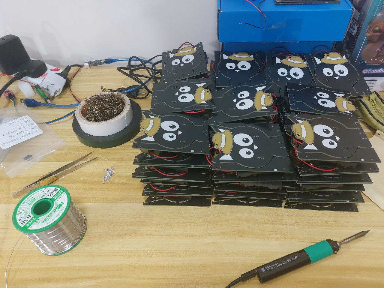
This might vary significantly depending on skill level and badge, but knowing the assembly time is important to account in the timeline. There's the case of leaving it as an exercise to the participants, but this also means that the participants would be less likely to play around with all the features of the badges (+ less fun). For planning, I dedicated 1 week to assembly, which worked out well enough.
The summit's badges were assembled during GreyCTF Finals itself with the help of more people (thanks so much guys), and it was a good way to kill time during the CTF.
4.3 CTF Logistics Issues
For our CTF, we had a few glitching challenges, and as such we needed to provide wires for them to do the glitching. I ended up cutting 2 solid core wires per team for them to use in the glitching challenges.
There were a rough list of issues during the CTF itself such as
- Using the Serial Monitor
- Many participants were (surprisingly) confused on how to use the Arduino IDE as a serial monitor. I had to guide participants on the initial steps
- Needing to bend the pins for the OLED.
- I did put it in my brief and my slides, but some of the instructions didn't exactly get through.
- Needing USB Cables
- We did inform everyone to bring a USB C cable (for their own badge), but as some challenges need 2 USB cables (2 badges), we didn't manage to account for that. We could have been clearer in our instructions/ provided extra USB cables for lending (which we did)
- Bricking the badge
- This was more unexpected but patching the binary was another path i should have thought about it harder. However, the affected teams were small, about 3 or so
For Hardware Challenges, it is important to have someone on site with the required tools (debugger, wires etc.) who is able to quickly respond to any issues. The onsite presence helped as I had people needing help at 12am that night, and I could fix their problems.
4.4 Timeline
The overall timeline worked out quite well. Here was a rough timeline.
| No. | Week | PCB Design | Firmware | Ordering | Activity |
|---|---|---|---|---|---|
| 1 | 20/5/2024 | Set up & ideation | |||
| 2 | 27/5/2024 | Routing | |||
| 3 | 3/6/2024 | Routing (minor) | My Japan Holiday | ||
| 4 | 10/6/2024 | Prototype 1 | Research | Order 1 | |
| 5 | 17/6/2024 | Prototype 2 | Order 2 + Components | ||
| 6 | 24/6/2024 | Setup codebase | |||
| 7 | 1/7/2024 | Prototype 3 | Base - USB + LED | Order 3 | |
| 8 | 8/7/2024 | OLED +Menus + Challenges | Final Order | ||
| 9 | 15/7/2024 | Bootloader + Challenges | |||
| 10 | 22/7/2024 | Assembly | Final Touches | GreyCTF Finals |
Preparing backup plans was also important, not just for alternative measures, but just to keep my mental sanity in case everything breaks. If I failed to get the STM32 up, the badge would just be simple LED lights. If even that failed, we just wont have the badge/ push back the badge to GreyCTF Summit (which would be sad but we have 2 extra weeks to fix things).
4.5 GreyCTF Summit
I've prepared 3 challenges
- Updating the firmware for me (because I added things to the firmware last min)
- Solving one of the onboard challenges
- Controlling a Servo using the timers
However, due to time constraints (and manpower), we only could do 8 people at a time, and cut back to just the first challenge, each taking 20min, and didn't have much time to expose others to hardware tinkering.
5. Overall
This was a fun project where I learnt a lot. Thanks to everyone who helped me make this possible! It's the sponsors who make this possible, so please do sponsor us for the next GreyCTFs so that we can keep doing stuff like this!.
I'm glad that the reception was positive by the participants and that the nights looking at GreyCat were worth it!
Badge for next GreyCTF? (If i have time)
OSINT
Other Badges for Inspiration
- SINCON
- Reloaded - (I owned one and didn't solve any challenge lmao)
- 2024 - https://www.hackster.io/HacksFromPanda/the-iced-gems-biscuit-badge-sincon-bb1308
- Cyberthon 2024
- ESP32-S3
Past GreyHats Badge for X-CTF 2016